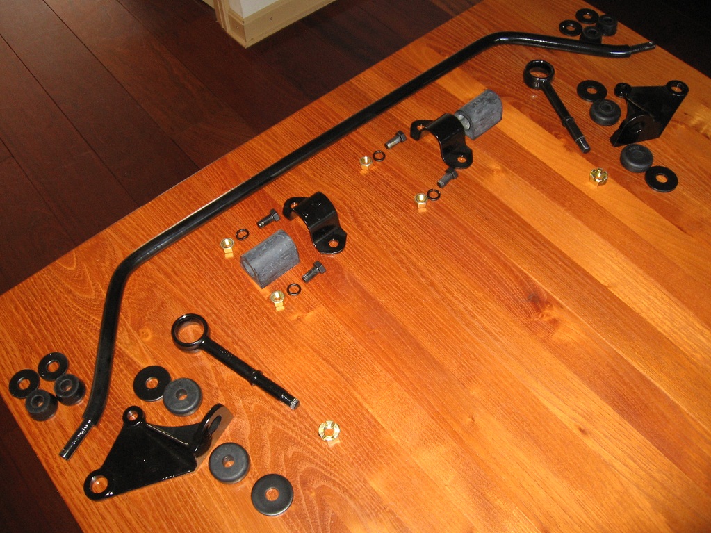
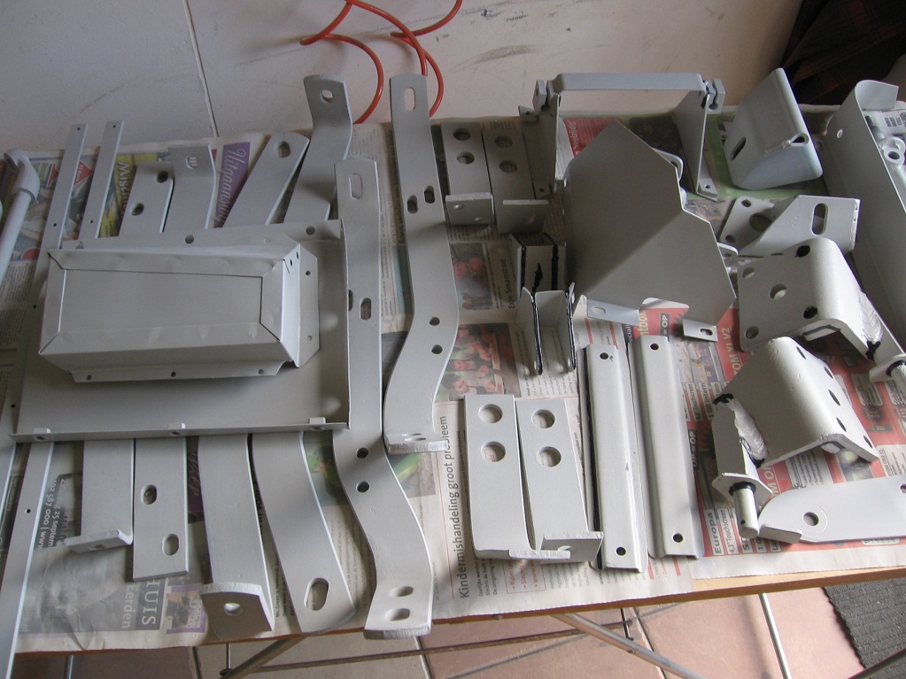
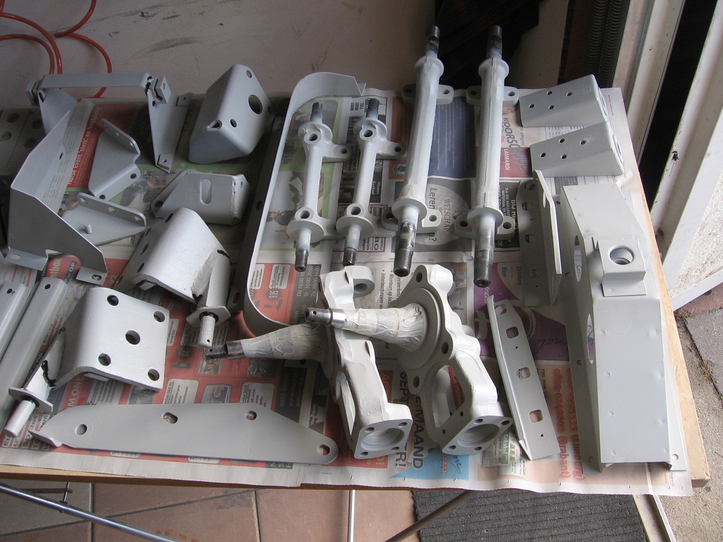
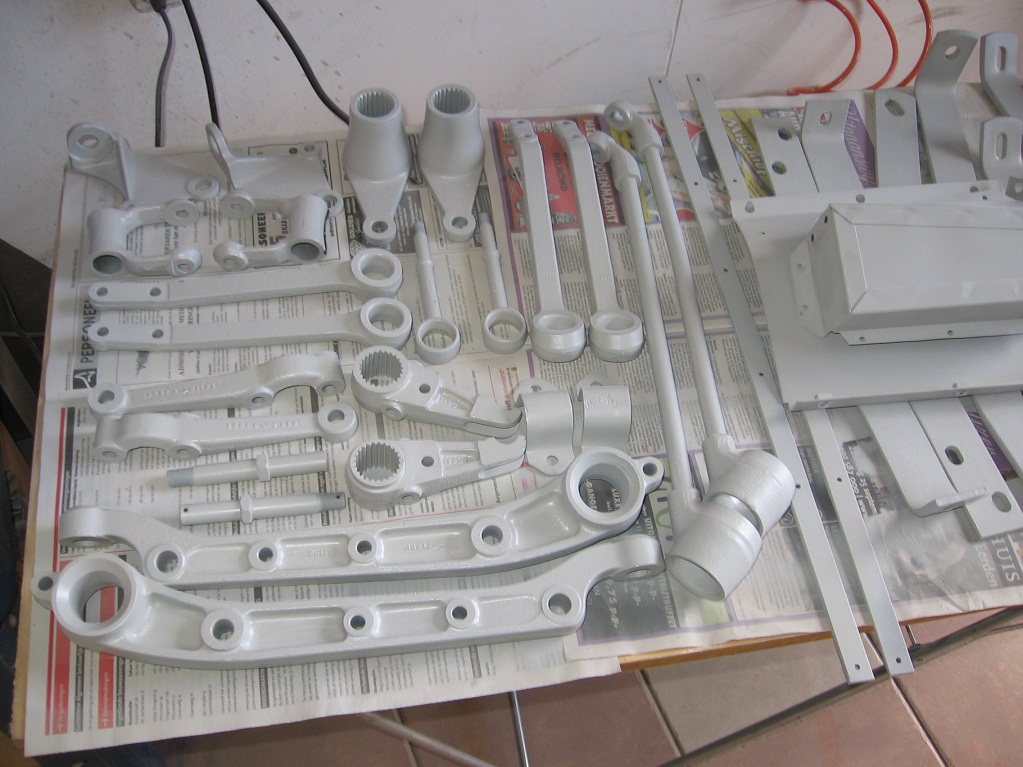
All separate parts used to rebuild the anti roll bar
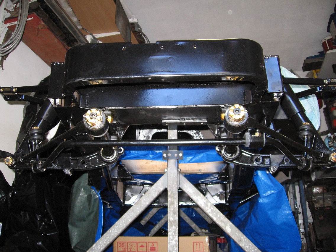
The original bell housing was corroded badly and one of the previous owners has made a square hole in the bottom. Most probably to inspect the clutch or do some kind of repair without removing it from the engine. I found a nice replacement in the UK as can be seen in the next picture.
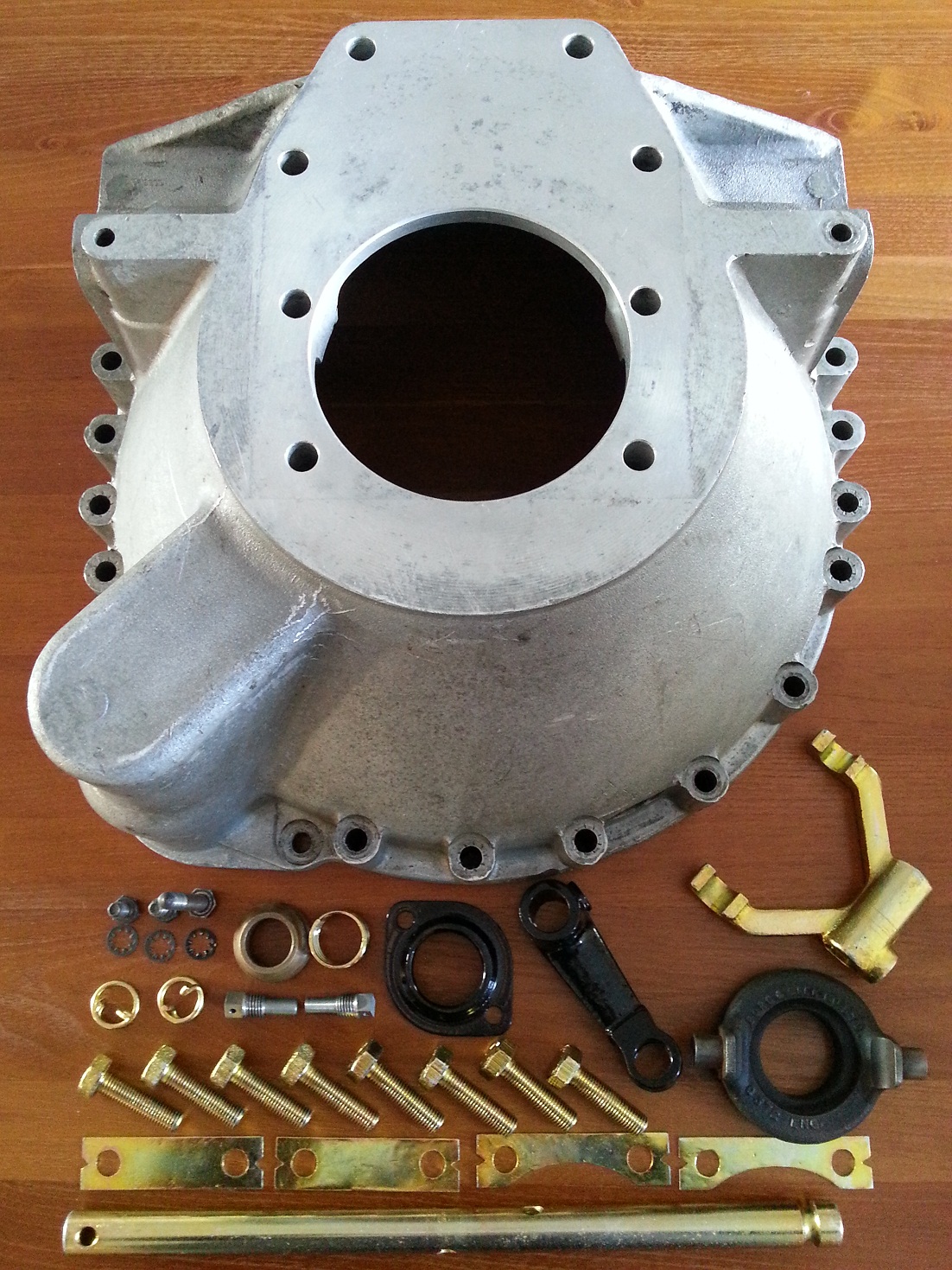
Parts needed to assemble the bell housing
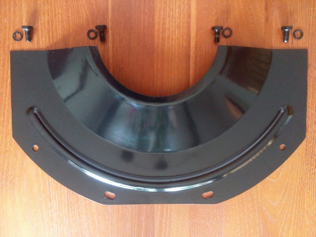
Plate to protect the clutch house internals
In the next picture the assembled gearbox has been mounted onto the bell housing. The clutch fork and clutch bearing can bee seen on the photo in more detail. The next step is assembling the top cover of the gear box. When this part is finished everything can be bolted, together with the clutch and pressure plate, to the engine. The protection plate must be mounted when the engine and gearbox are bolted together.
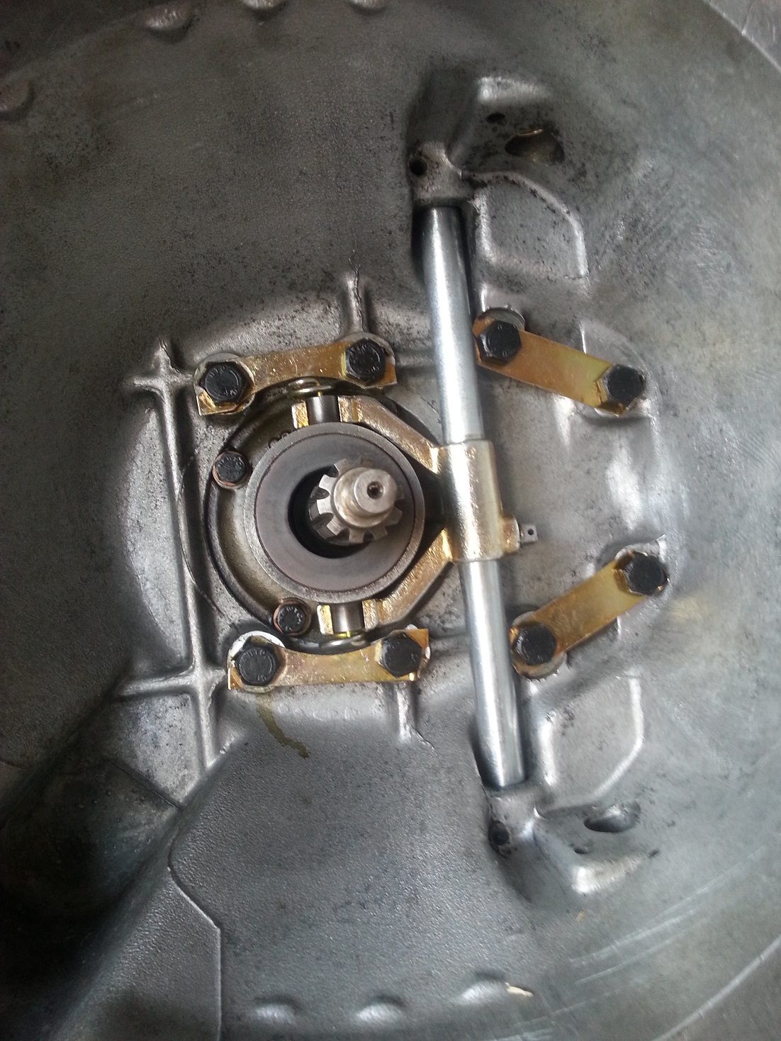
Clutch fork detail

Finished gearbox and bell housing
Because the flywheel, pressure and clutch plate can’t enter the bell housing when the cover plate is mounted already, it will be done after it has been bolted to the engine block. This cover plate prevents that water, crease and dirt enters the bell housing and will have a bad influence on the clutch operation.
]]>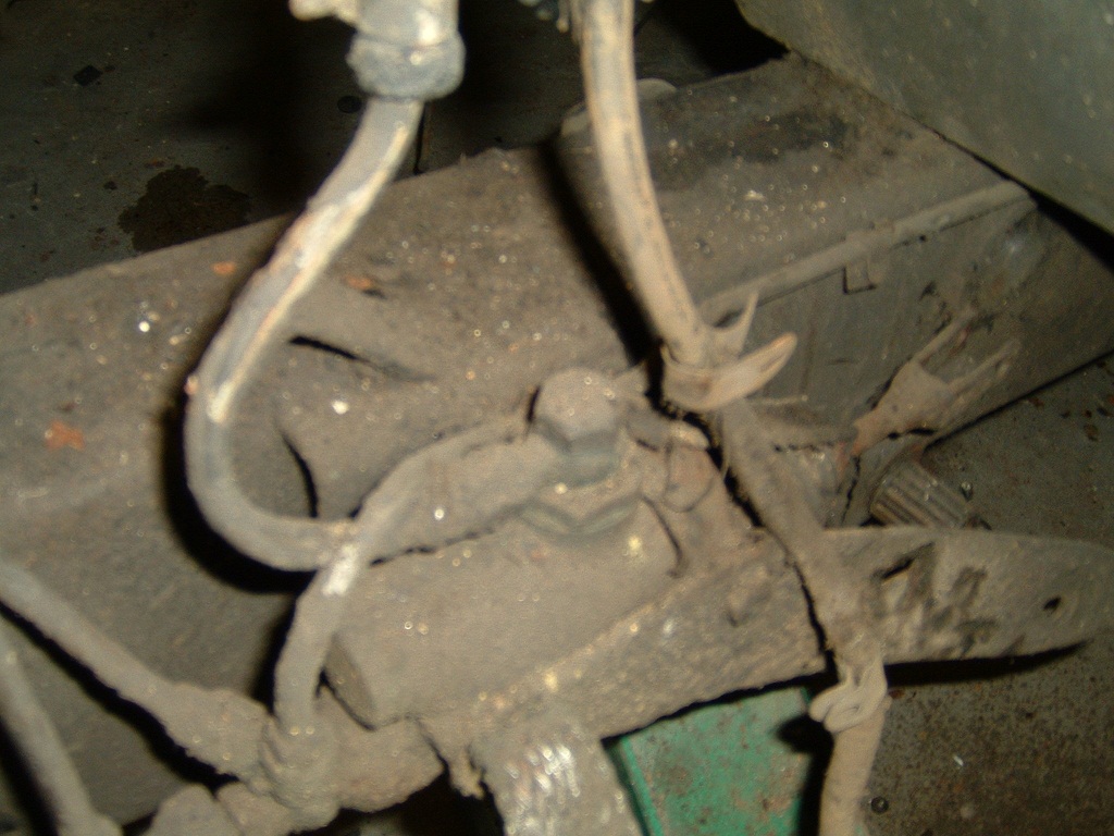
Before
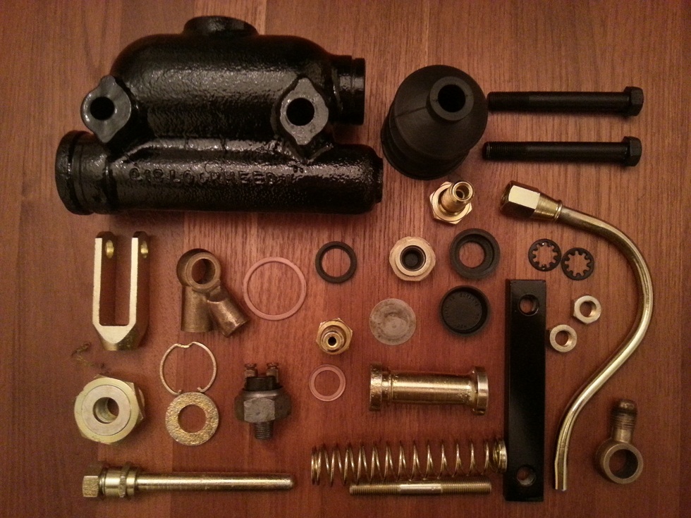
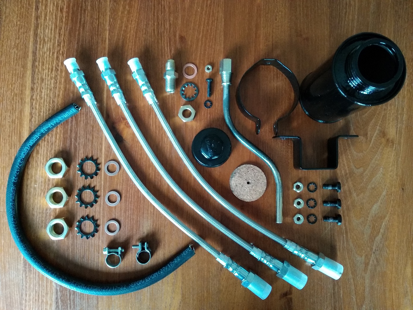
All separate parts used to rebuild the brake cyclinder
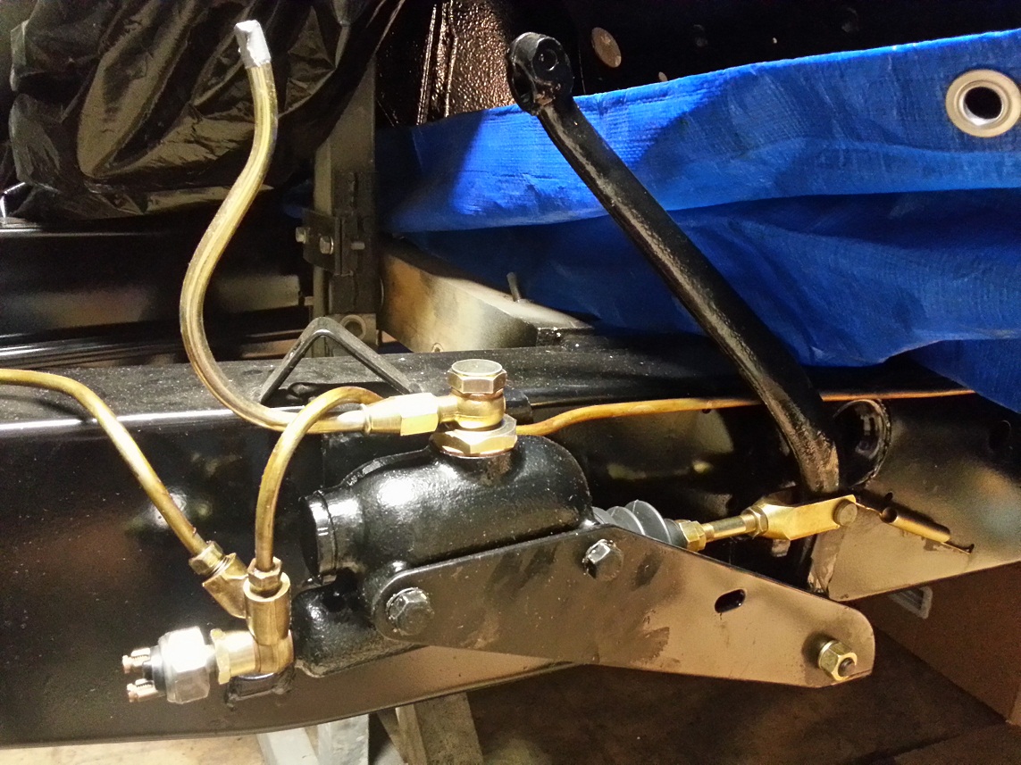
After
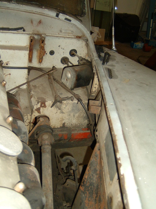
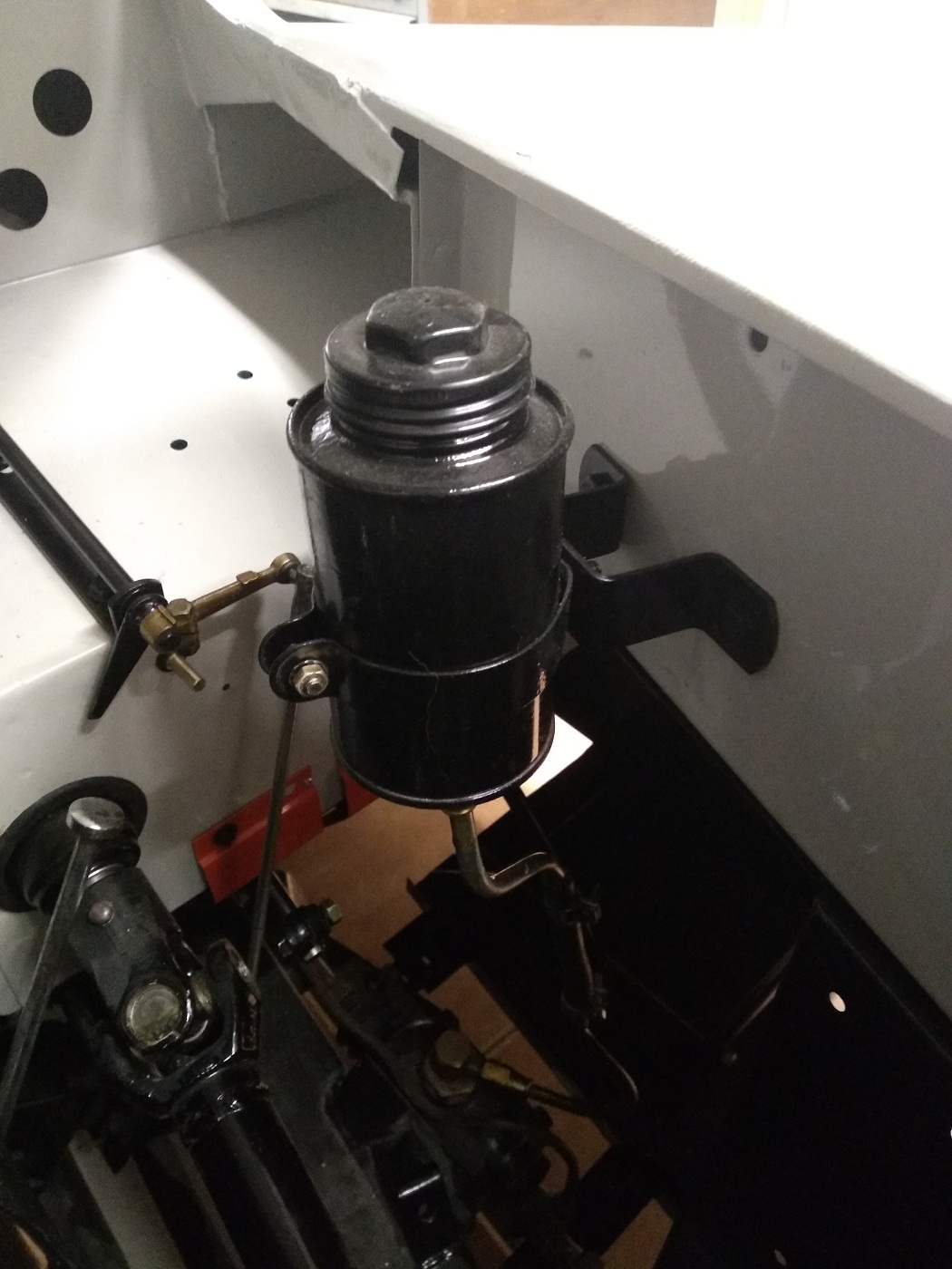
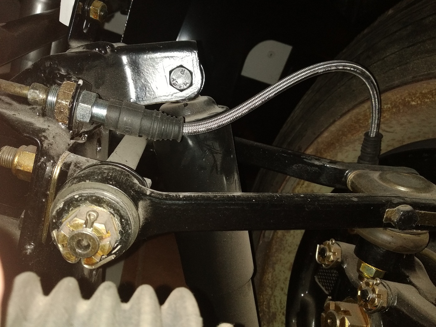
After everything has been painted and new parts bought (brake hose and clamps) everything can be mounted on the car again.
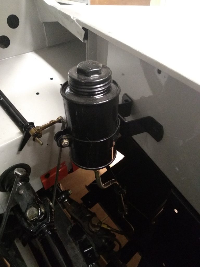
Brake reservoir installed 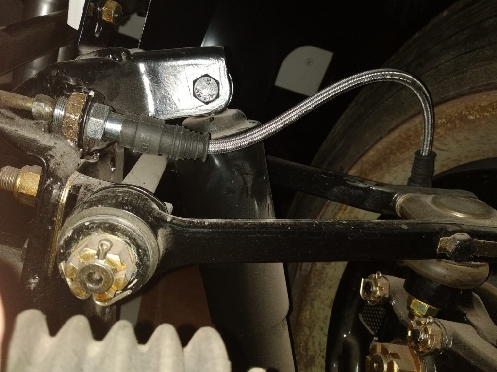
Flexible brake hose to the left front wheel
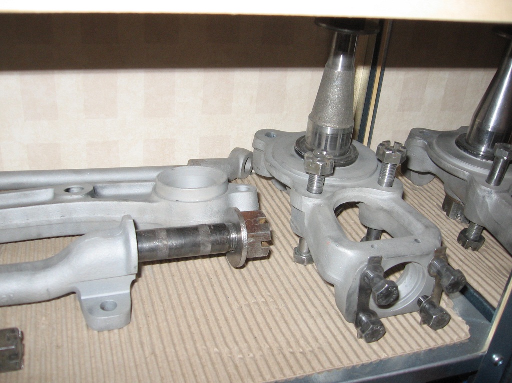
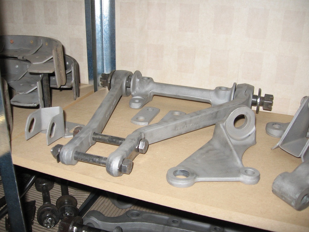
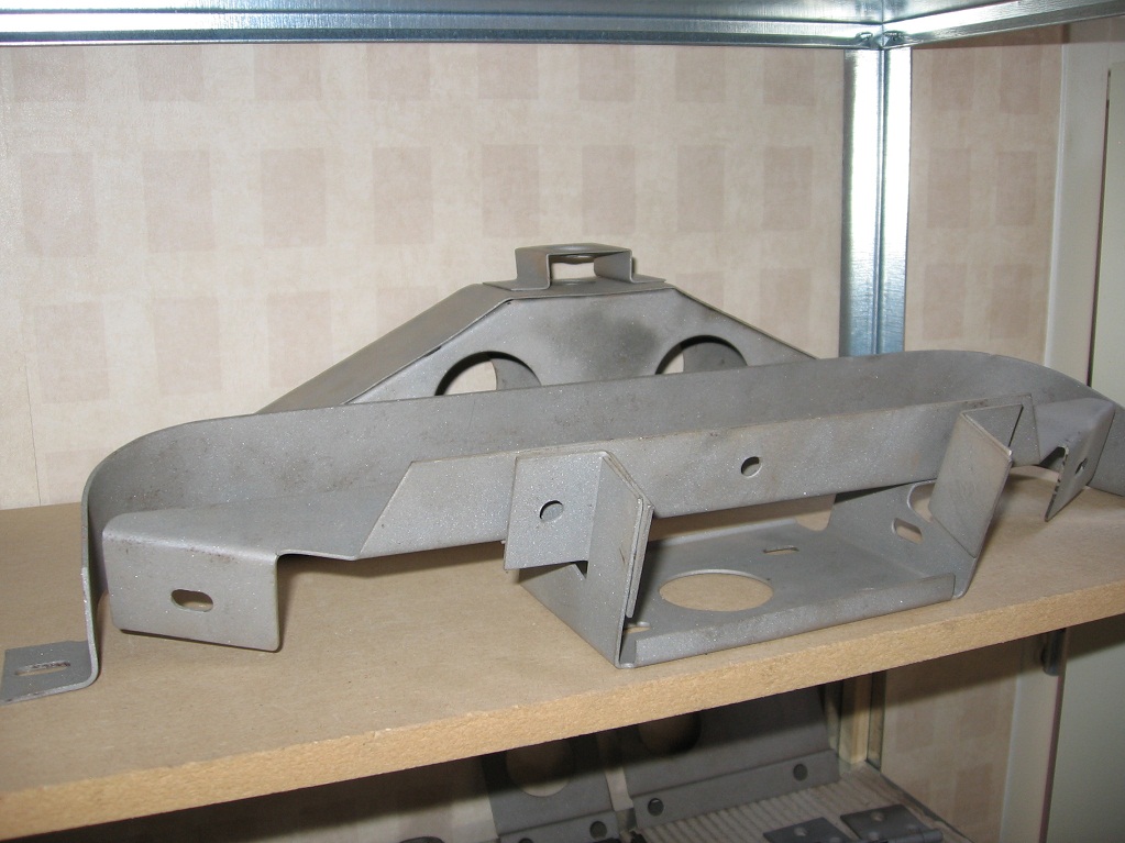
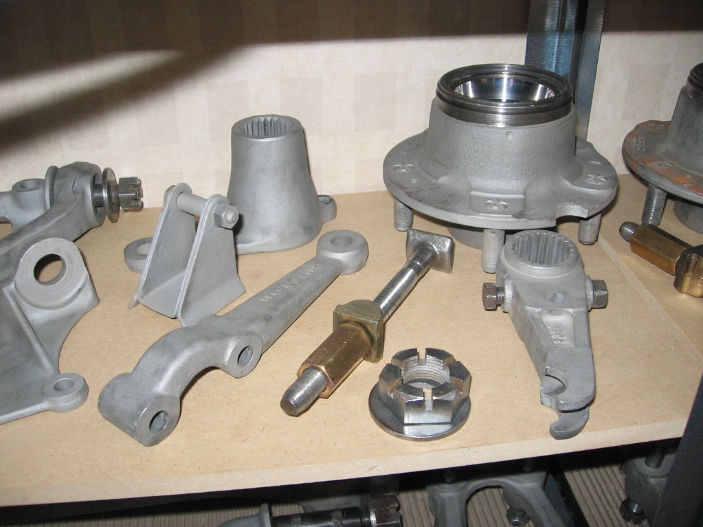
After the decreasing process as been finished all parts are bead blasted until the whole surface is rust free, as you can see on the following pictures.

The original clutch unit which was mounted on the flywheel
So first I disassembled everything (be careful with removing the three nuts, there is a lot of pressure due to the twelve strong springs). Cleaned everything with glass bead blasting and sprayed everything with a new fresh layer of paint. I used special paint for the parts who can become very hot (< 800℃)
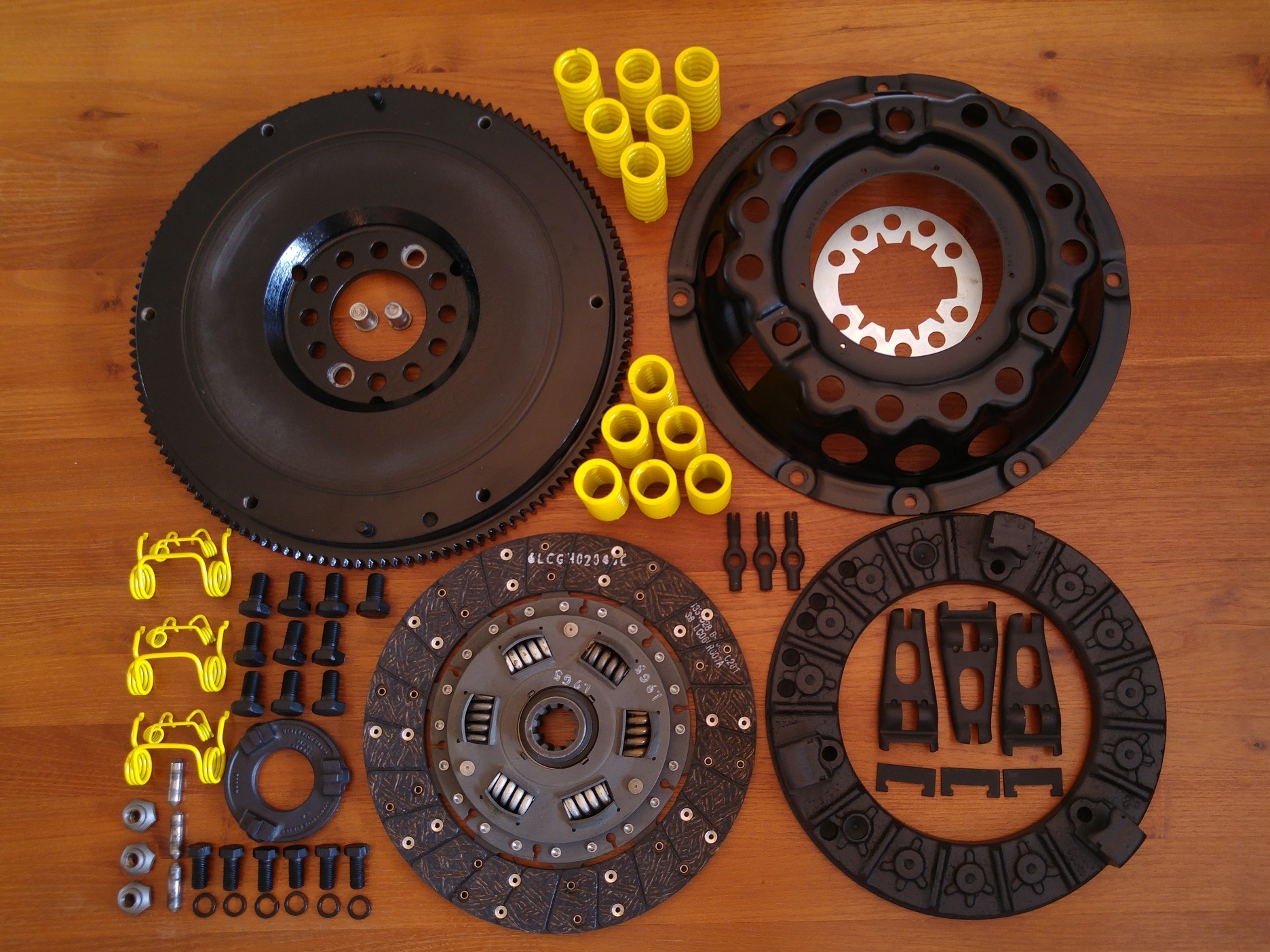
The original paint on the springs, who will deliver the pressure to the clutch plates, where not visible anymore. But in the documentation is stated the they should be painted yellow.
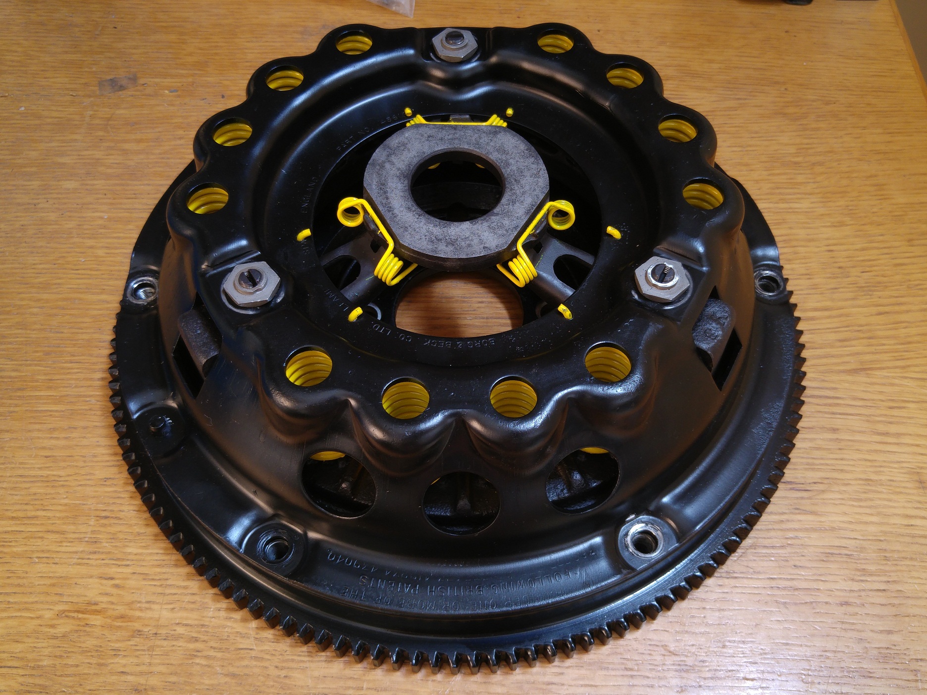
The restored clutch unit, ready to be mounted
I didn’t know if it was really necessarily but I placed the cover on the same location as it was originally. During the assembly I noticed that the pressure plate has been balanced in some way (In the second picture you can obvious the have drilled 7 extra holes to remove some material).
]]>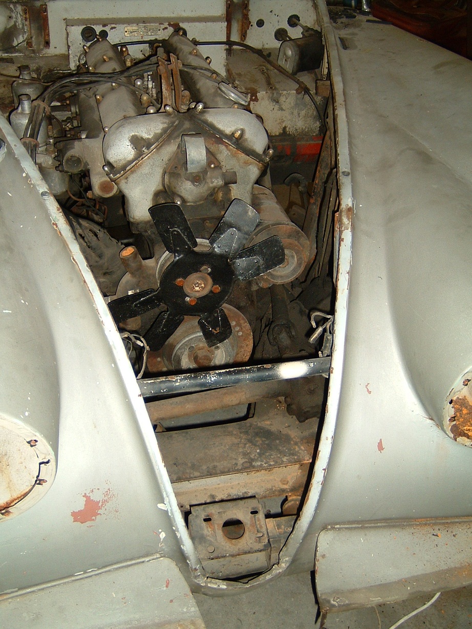
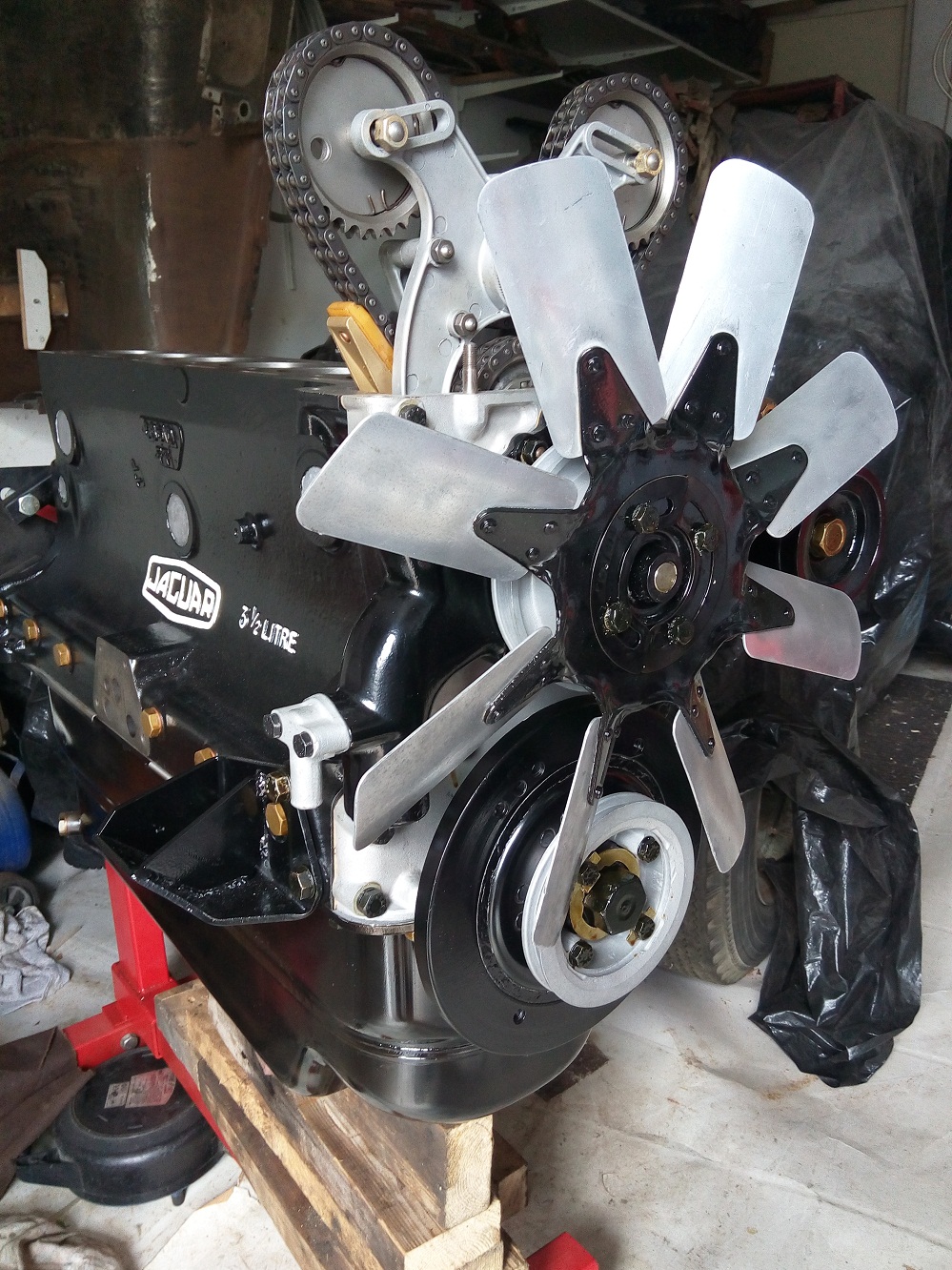
Front side of the engine with wrong fan blade
Originally the engine inside my car was equipped with the wrong type of fan blade. Instead of the xk140 type blade (symetric) it was equipped with the xk120 fan blade (a-symatric)
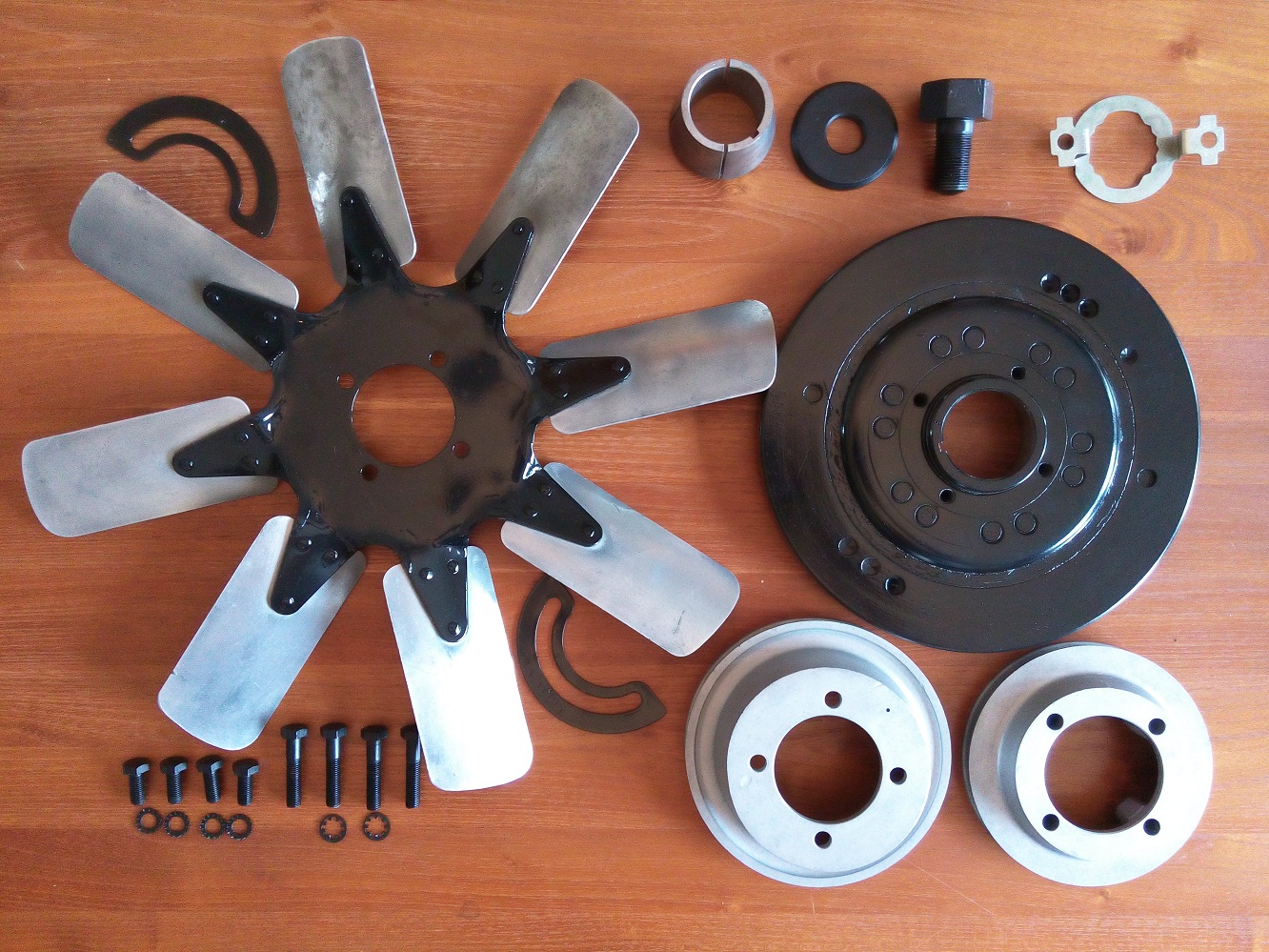
All parts needed to rebuild the fan blade installation
With the fan blade mounted the front of the engine is now almost finished. Only the cylinder head is missing, which is still at the machinery.
It is not completely clear if the aluminium blades should be painted black or not, the documentation is not very consistent. Most original pictures/photos show the bare aluminium without any paint.
- Mains bearings (6/100, still within specification)
To prevent honing the crankshaft(I can only be done twice, and it will get less riged) I accept the play as it is. - Thrust washers (with one STD and one oversize 11/100)
- Big-end bearings (4/100, still within specification)
- Small-end bearing (No notable play)

Original uncleaned bottom view of the crankshaft
All separate parts are thoroughly cleaned and the following parts are bought new:
- New main bearings (STD)
- New big-end bearings (STD)
- New thrust washers (STD + oversize)
- New piston set (complete with 4 rings, gudgeon pin and circlips)
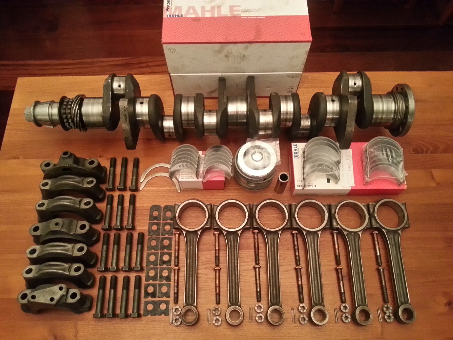
All cleaned and new parts needed to mount the crank shaft and pistons
Remarks:
- Don’t forget the oil sealing ring at the rear block before the crankshaft is mounted.
- Mount the bearing so the indicators will match (they are all numbered and the engine block also has these numbers stamped into the casting) Numbers should be kept at the inlet side.
- The pistons are number from 1 until 6 starting from the backside of the block
- The piston numbers are stamped into the connection rod and the big-end bearing cap
- The piston numbers should be readable from the exhaust side
- The compression piston rings should be mounted in opposite direction 0 and 180 degrees. I also mounted the oil scrapper rings at 90 and 270 degrees.
- When piston 1 and 6 are in the TDC position the distributor shaft
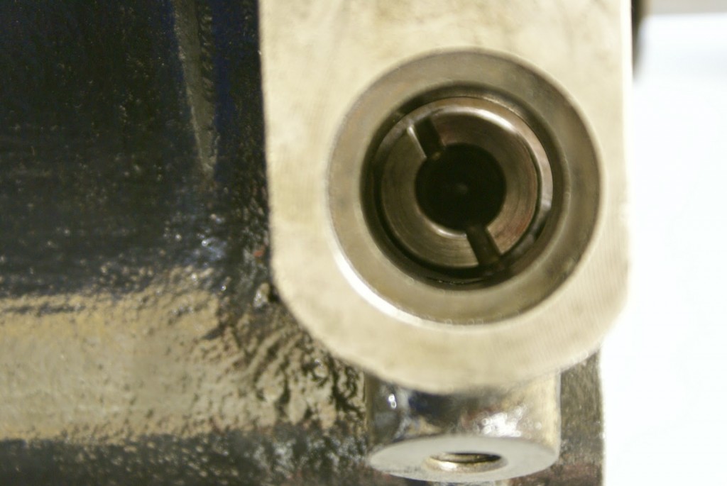 should be positioned at 5 to 5. The distributor shaft will make a half rotation when the crankshaft has made one.
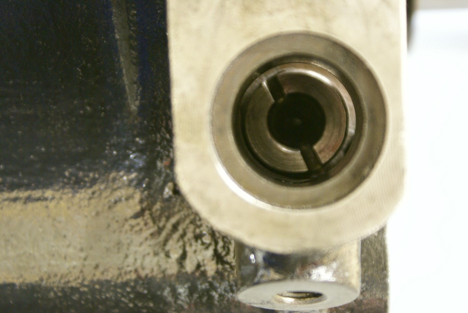
- When the timing chain is connected to camshaft make sure the distributor shaft is positioned as shown on the picture.
(Remark the notch is positioned left from the middle at 5 to 5)
Because I found some pictures, original made in jaguar factory with painted text, I painted the “Jaguar” logo and the text “3 1/2 litre” in white.
Bellow the engine block with the pistons and crankshaft completely mounted.
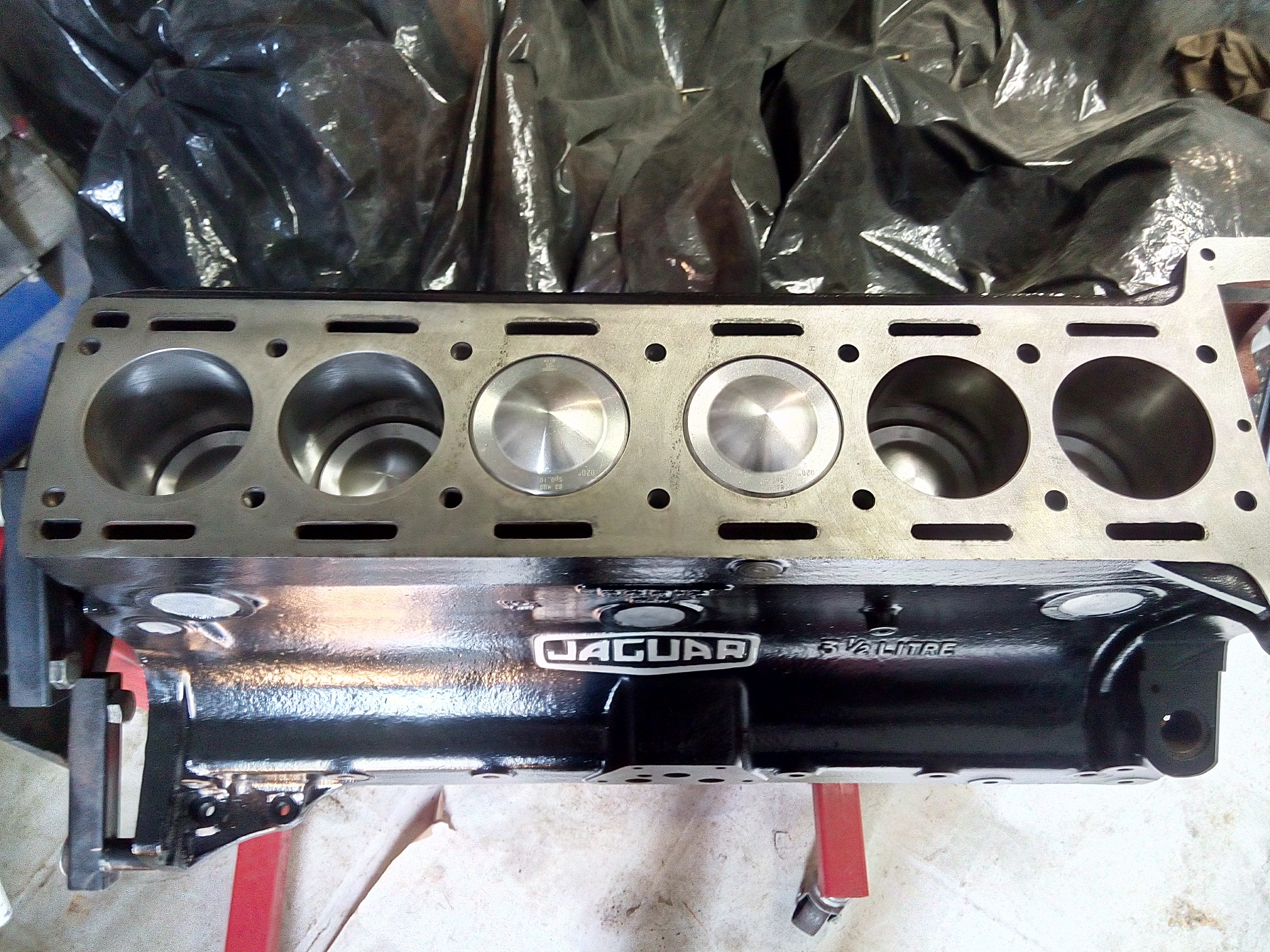
Engine with the crankshaft and pistons installed
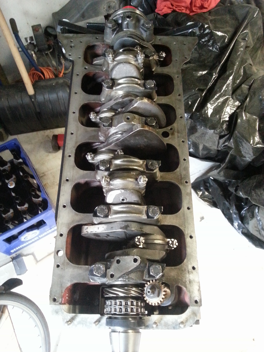
Crankshaft, bearing caps and connecting rods installed
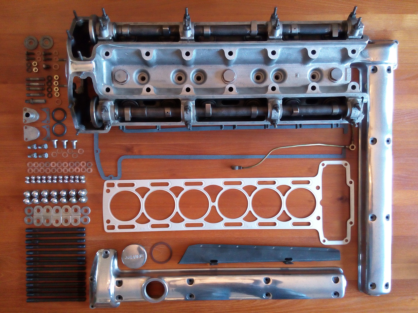
All parts needed to finish and mount the cylinder head on the engine

All parts needed to mount the exhaust manifolds
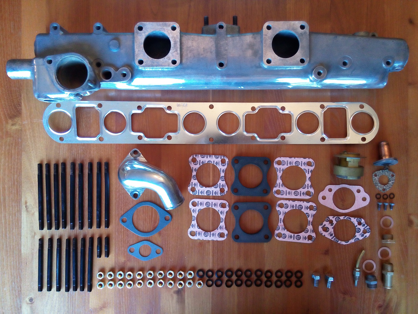
All parts needed to mount the inlet manifold

All parts needed to rebuild the breather housing
Now that the cylinder head and exhaust manifolds are mounted it already begin to look at a complete Jaguar XK engine. The exhaust manifolds are bought via ebay in the USA for only $50 (inclusive national shipping ) A friend of the neighbors was kindly enough to take them for me to the Netherlands. Because the enamel still looks like new so I assume that the previous owner has redone this in the past.
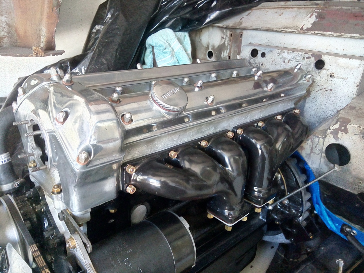
Cylinder head and exhaust manifold mounted
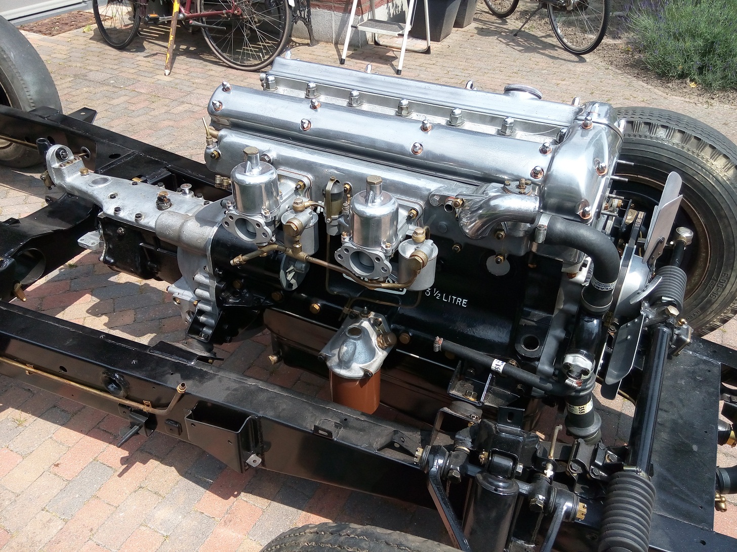
Cylinder head and inlet manifold mounted
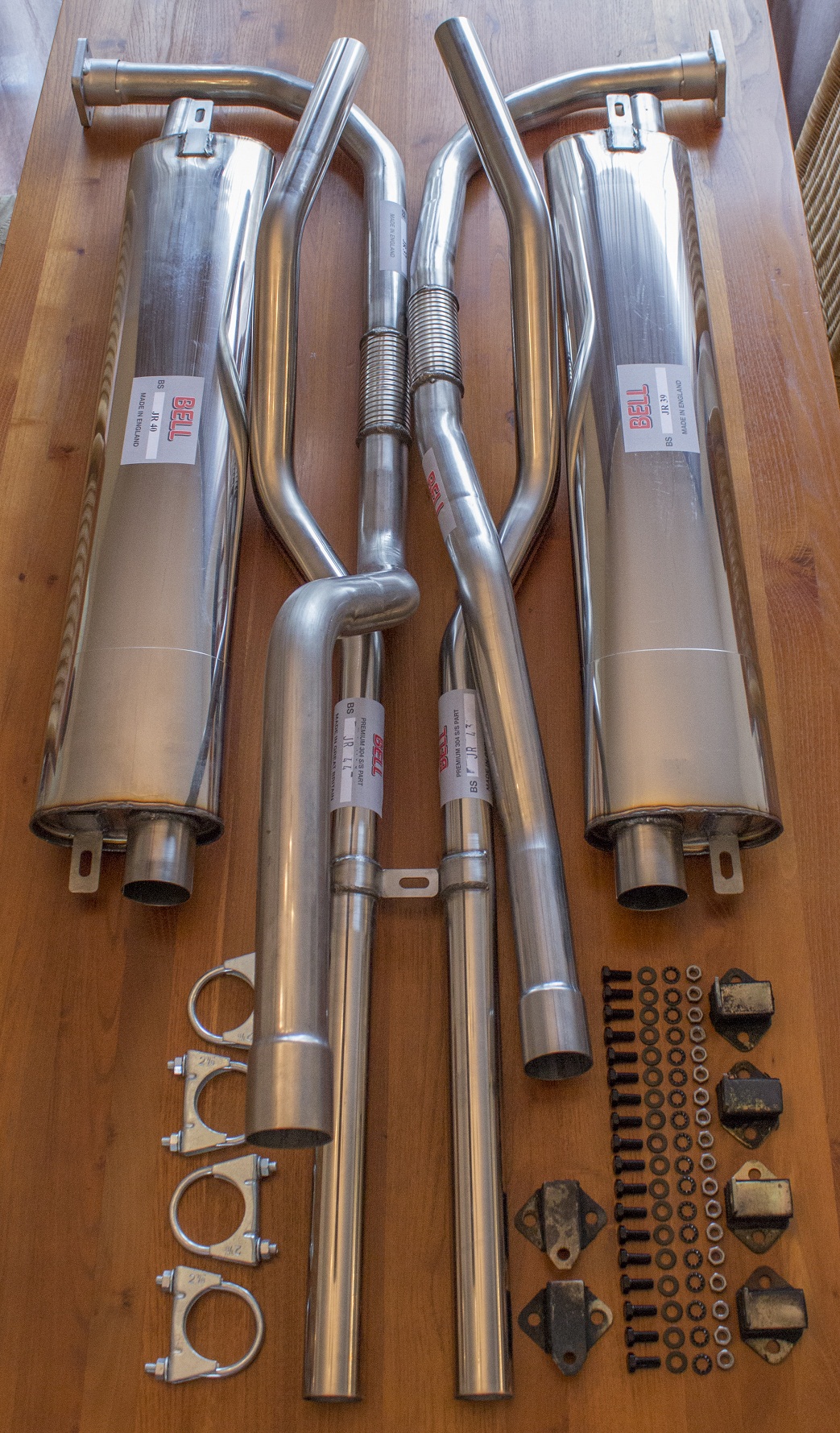
The new dual exhaust from Bell (BSS-JR-003, XK140/XK150 LHD manual) consists of:
- BSJR37 Front pipe left
- BSJR38 Front pipe right
- BSJR39 Silencer left
- BSJR40 Silencer right
- BSJR43P Tail Pipe left
- BSJR44P Tail Pipe right
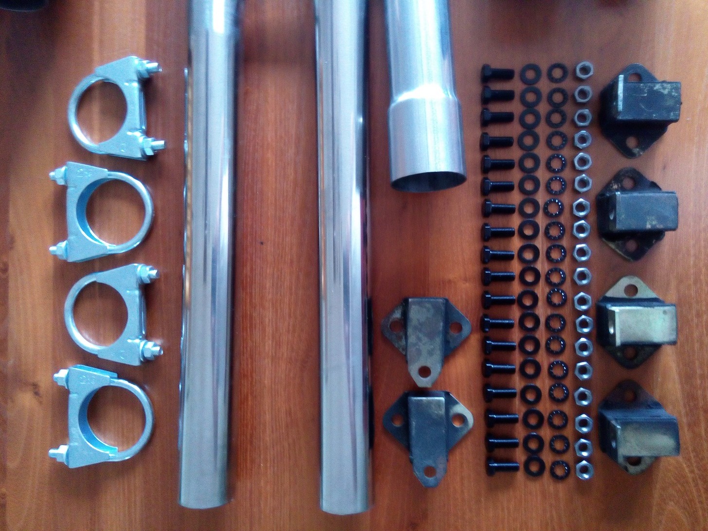
Nuts, Bolts and Clamps
The clamps, needed to fasten the exhaust pipes to each other have different diameters, 58mm for the front side of the silencer and 48 for the rear side.
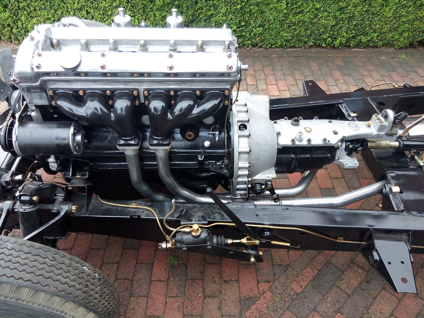
Dual exhaust mounted onto the manifold