Peter

dec 312014
 

This parts covers the flywheel and clutch  located between engine and gearbox. It is also used to mount the starter motor which makes a connection to the ring gear on the fly wheel.

The original bell housing was corroded badly and one of the previous owners has made a square hole in the bottom. Most probably to inspect the clutch or do some kind of repair without removing it from the engine. I found a nice replacement in the UK as can be seen in the next picture.

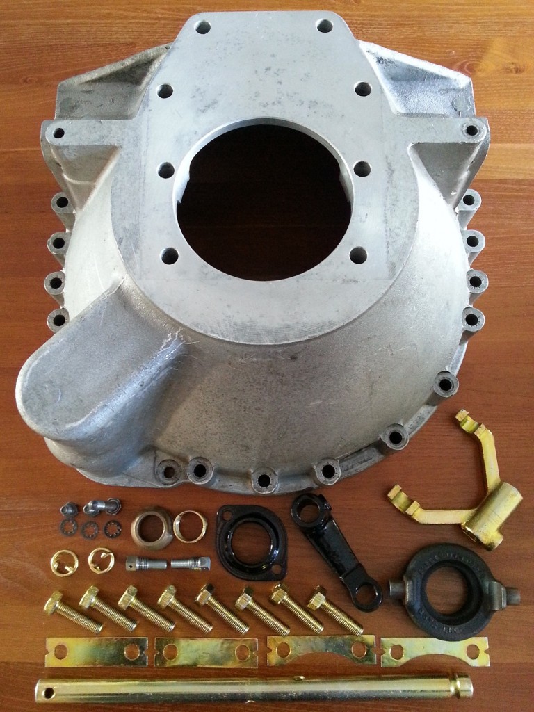
BellHousingParts

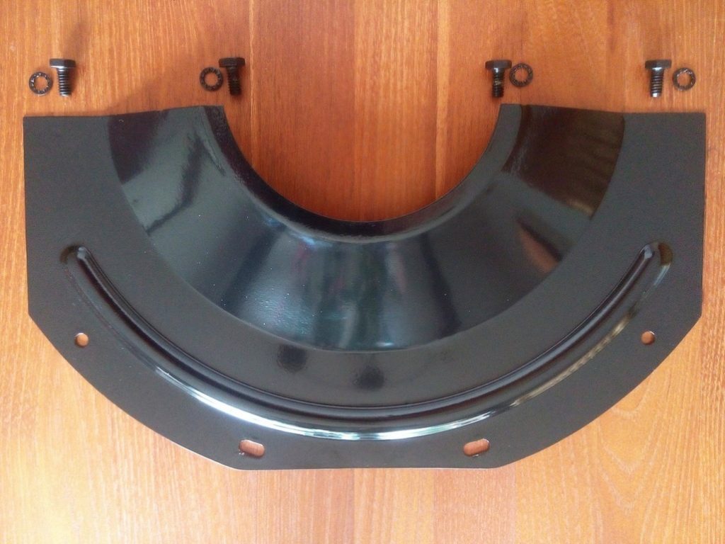
Parts needed to assemble the bell housing

Plate to protect the clutch house internals

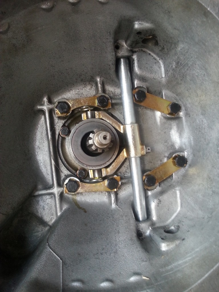
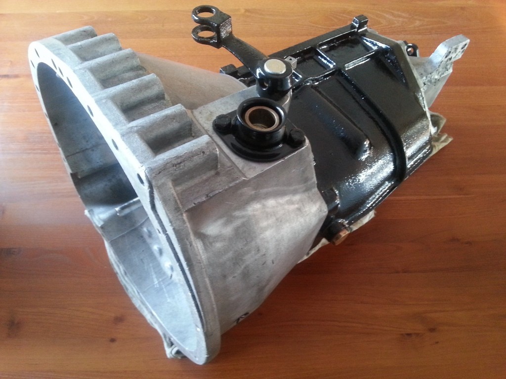
In the next picture the assembled gearbox has been mounted onto the bell housing. The clutch fork and clutch bearing can bee seen on the photo in more detail. The next step is assembling the top cover of the gear box. When this part is finished everything can be bolted, together with the clutch and pressure plate, to the engine. The protection plate must be mounted when the engine and gearbox are bolted together.

2014-12-29 12.55.04

Clutch fork detail

2014-12-29 12.56.12

Finished gearbox and bell housing


Because the flywheel, pressure and clutch plate can’t enter the bell housing when the cover plate is mounted already, it will be done after it has been bolted to the engine block. This cover plate prevents that water, crease and dirt enters the bell housing and will have a bad influence on the clutch operation.
 Posted by at 12:59
dec 282014
 

50percentWhen I bought this car 6,5 year ago my first estimation was to finished this project in 5 year. I lot of people  in my environment  respond like this; 5 YEAR, so long!

Today the progress has crossed the 50% boundary. My current impression is that the last 50% will go a bit faster.  In the first 50% the work meanly consists of

  • Disassembling
  • Cleaning
  • Find missing parts
  • Research
  • Figure out which parts are used where
  • Assembling the rolling chassis (except the engine)
  • Bodywork repair I

During the last 50% i will need to do;

  • Finishing the body work repair
  • Electrical installation
  • Assembling bodywork and interior
  • Lining
  • Finishing the rolling chassis; Carburetor,  Dynamo, Starter, Waterpump, Oil cleaner and Engine
 Posted by at 16:42
dec 202014
 

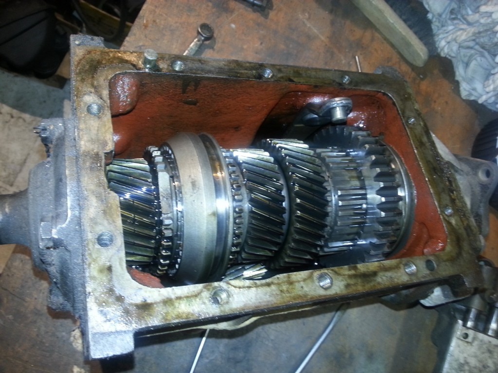
GearboxInternalAfter removing the gearbox cover I was pleased to see that there was still 0,5 liter of oil inside. All the gears looks still great.

The bearing of the incoming axle was blocked for some reason but I already planned to replace all bearing anyway.

The needles bearings where also not so good but the bearing surface was still in good shape.

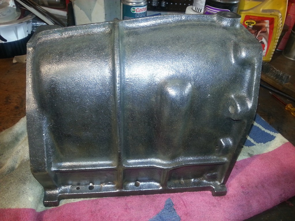
After all internals where cleaned, checked and stored I started with cleaning the gearbox cover.

I will leave the gearbox cover as it is for the time being. I don’t want to disassemble to much at the same time be able to assemble everything as it should.

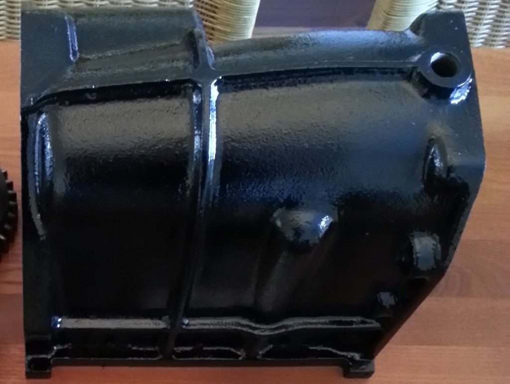
Gearbox Cleaned Gearbox Painted


After the outside gearbox cover was decreased and all rust removed, it could be painted epoxy primer and several layers of black paint.

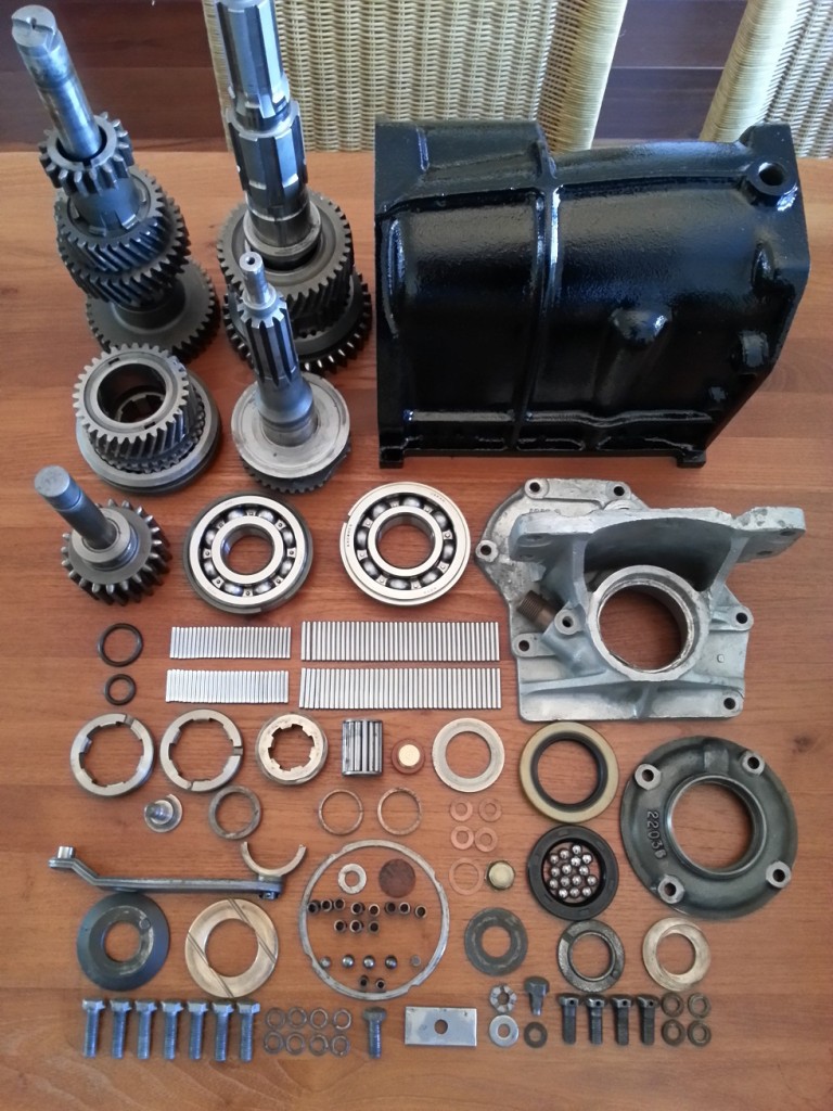
Gearbox Parts

All separate parts used to rebuild the gearbox without cover

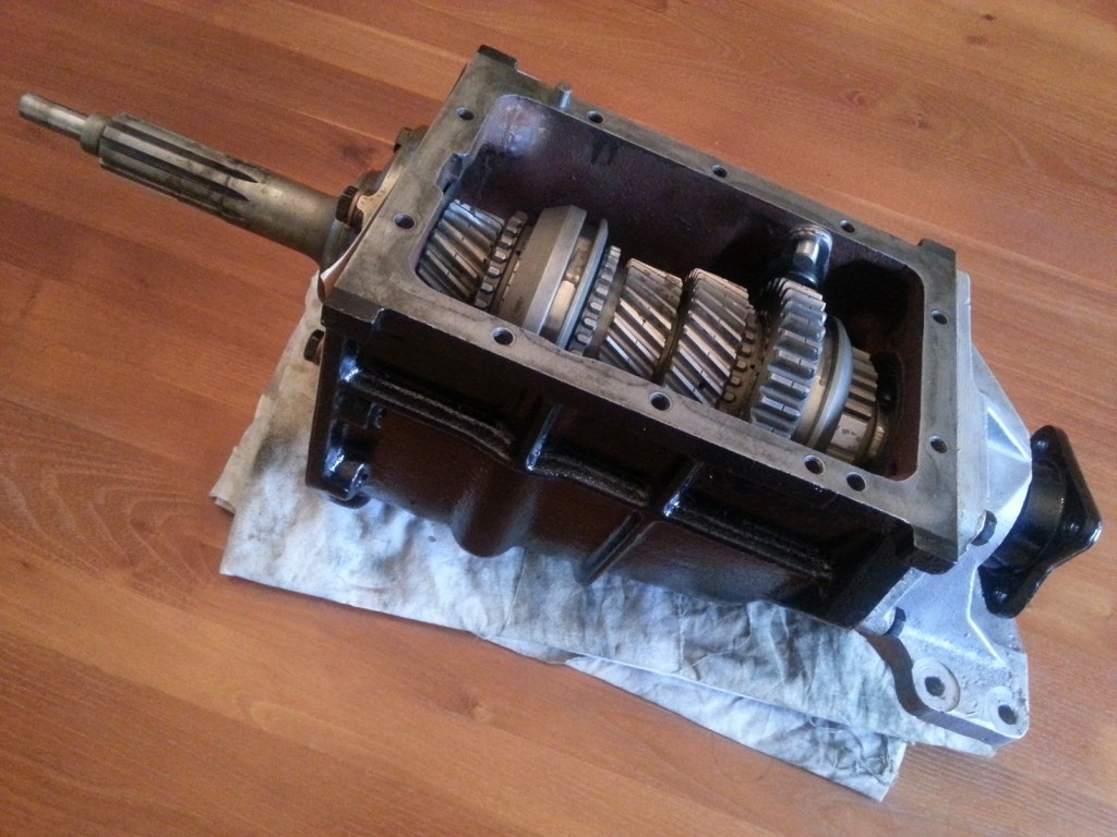
GearboxInternalFinished

Gearbox (without cover) mounted


 Posted by at 17:27
nov 302014
 

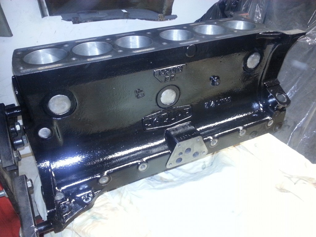
After I received the engine block from the revision company I started to remove all external rust. The dirt and crease was already removed before it went to this company. The outside of the block can now be sprayed with special engine paint (MOTIP engine paint black gloss) which can withstand 150 degrees.

Engine Painted

Due to experience from other XK restorers (replaced freeze plugs came loose) I decided to leave the freeze plug in place because they still look and feel very thick (it was not possible to make dents in them with a hammer). On the original block there where also no signs of leakage. The plugs didn’t show any damage/rust when inspected from the inside (via water channels)

The basis for the engine block is now finished and we can start with the following items (which will be handle in separate parts):

 Posted by at 16:08
aug 292014
 

Today I brought the cylinder-head and cylinder-block to “Rombouts revisie” in goirle.

The measured clearance:

  • Crankshaft STD with 15/100 mm clearance
  • Inlet Camshaft STD with no visible play
  • Outlet Camshaft STD with no visible play
  • Piston 1 STD with 15/100 mm clearance
  • Piston 2 STD with 15/100 mm clearance
  • Piston 3 STD with 15/100 mm clearance
  • Piston 4 STD with 15/100 mm clearance
  • Piston 5 STD with 15/100 mm clearance (after drilling to 75/100 mm still corrosion visable)
  • Piston 6 STD with 25/100 mm clearance (after drilling to 50/100 mm still corrosion visable)
  • To match play on the valve guides
  • Valve seats are worn and will be replaced by unleaded fuel types

.010″ = 10/1000″ = 0,25 mm = 25/100 mm
.020″ = 20/1000″ = 0,50 mm = 50/100 mm

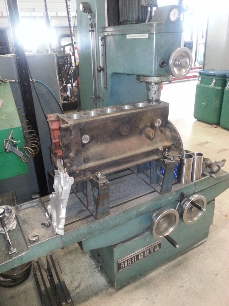
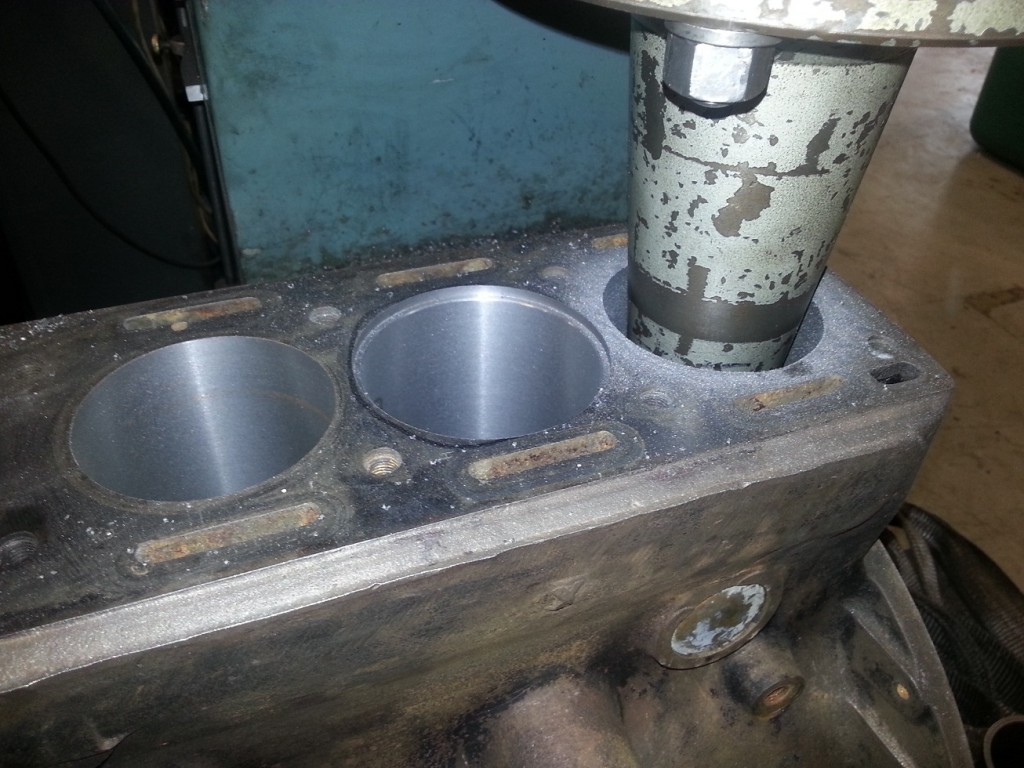
Engine Drilling Machinery Engine Drilling Detail

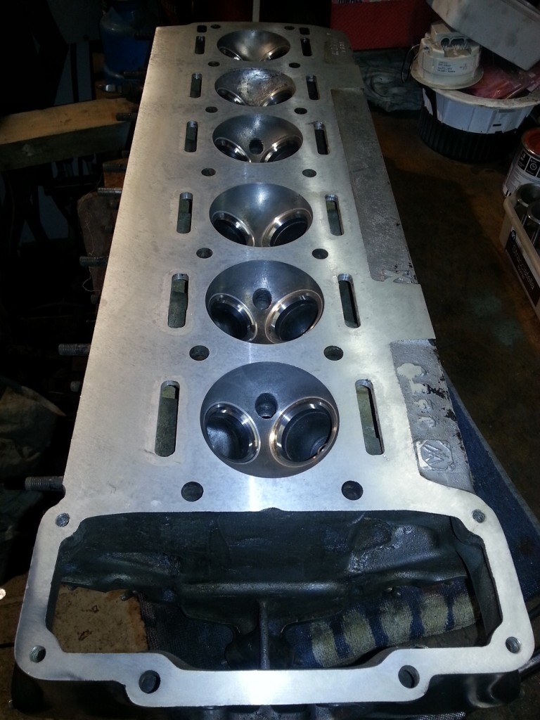
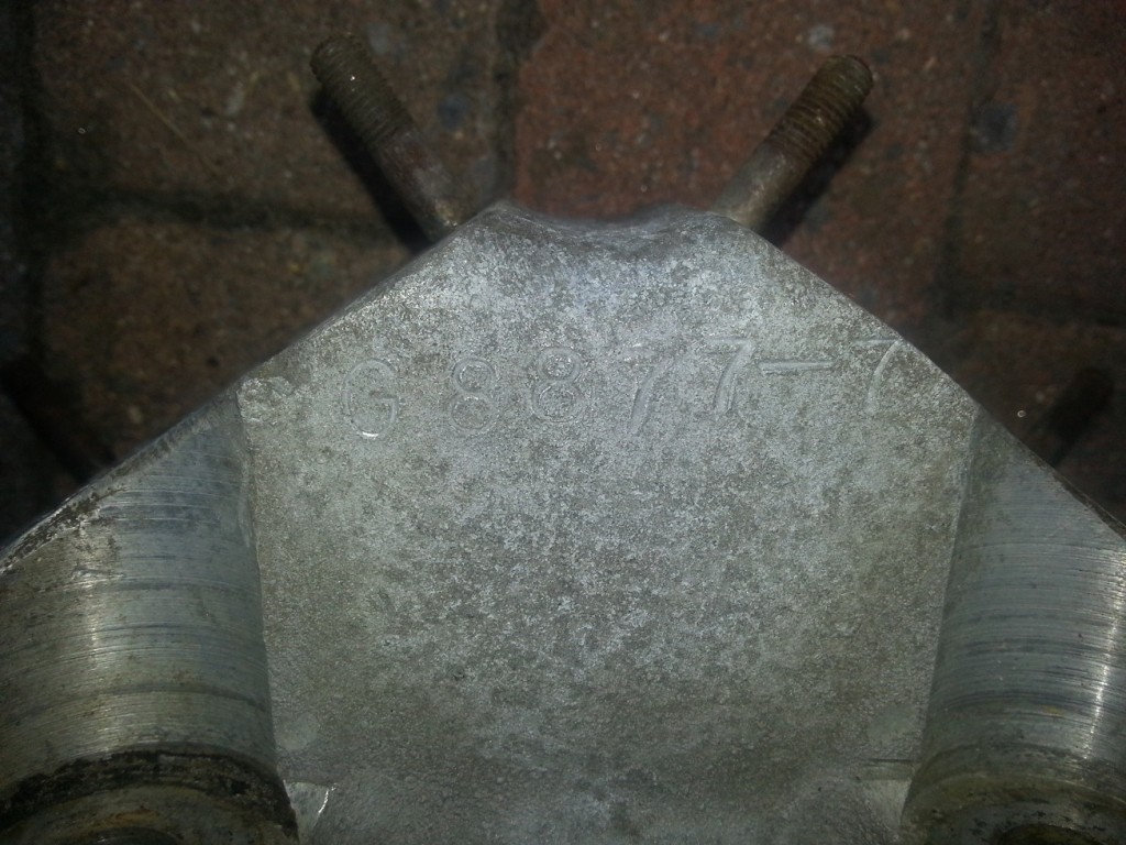
Before the actual revision started they executed a cylinder head water pressure test to discover possible water leakage. (Due to the visible corrosion in the cylinder head) The conclusion was that it already started to leak inside combustion chamber 5 at a very low water pressure level. The advise was to look for a different cylinder head due to the high corrosion level in combustion chamber 4, 5 and 6. So I brought my XK120 head for the same test and although the water channels where no so good, the combustion chambers where much much better. Because the head between the XK120 and XK140 are technically equal (except for the number stamped into the casting) I decided to take the XK120 head.

The valves from both heads (24 in total) are not usable anymore because;

  • 10 pieces are damaged by corrosion
  • 7 pieces are shortened to compensate the excessive valve seat wear.

Work for the revision company:

  • Re-sleeve cylinder wall 5 and 6
  • Drill all cylinders to +020
  • Flattening of the cylinder block
  • Water pressure tests on two different XK cylinder heads
  • Replace all valve seats with unleaded fuel types
  • Replace all valve guides
  • Flattening of the cylinder head
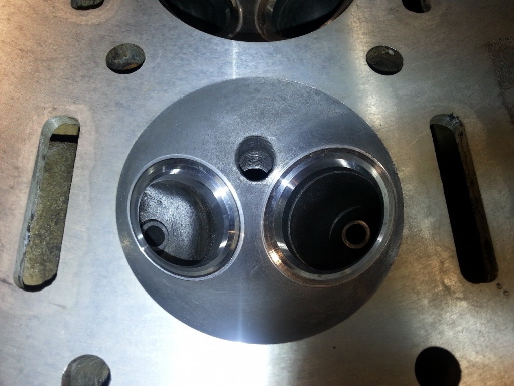
  • Welding all damaged water channels in the cylinder head (12 x)
    The discoloring around the water channels shows what has been welded

Cylinderhead Detail Cylinderhead

In the mean time I ordered the following new parts:

  • 6 Pistons oversize +20
  • 6 inlet valves
  • 6 exhaust valves
  • Crankshaft bearing
  • Thrust bearing
  • Big end bearings
  • Camshaft bearing
  • Bottom gasket set (including oil seals)
  • Top gasket set (including oil seals)

All preparation has been finished (10 october 2014), the assembly process can now be started.

 Posted by at 14:13
jul 022014
 

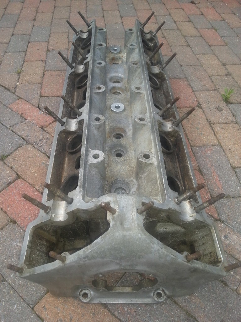
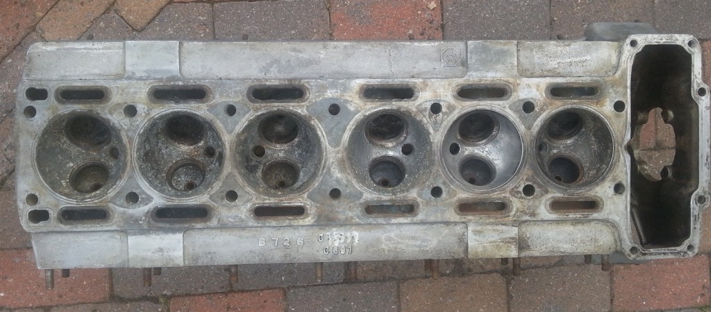
Cilinder Head

After all valves where removed and cleaned it was clear, that from the to heads (24 valves), a good set of valves could be combined. Some of the valves show corrosion damaged and can’t be used anymore. The corrosion in the water ports are not to bad and can be left as they are now.

CilinderHeadTop

CilinderHeadBottomCilinderHeadNumber
One tappet guide should be replaced because it is cracked (became visible  after cleaning)

Because one of the mounted camshafts (outlet) where from a XK120 (less valve lift) I bought an other one from a jaguar MK2 (C13081) Together with the mounted inlet valve is C13080 we have a matched set again.

Cilinder Block

After removing all main bearings and the crankshaft we could start removing the pistons.
Because the block has not be moved for over 46 years this was not a easy job. The first three pistons could be removed quite easily but the last three where deadlocked. After I applied penetrating oil and wait a couple of weeks, I managed to knock them one by one loose with a block of wood and a heavy hammer.

One of the six cylinder walls was badly damaged by corrosion.

All parts needed to rebuild the head and block are thoroughly cleaned and sorted, ready for the machinery.

 Posted by at 11:53
jun 102014
 

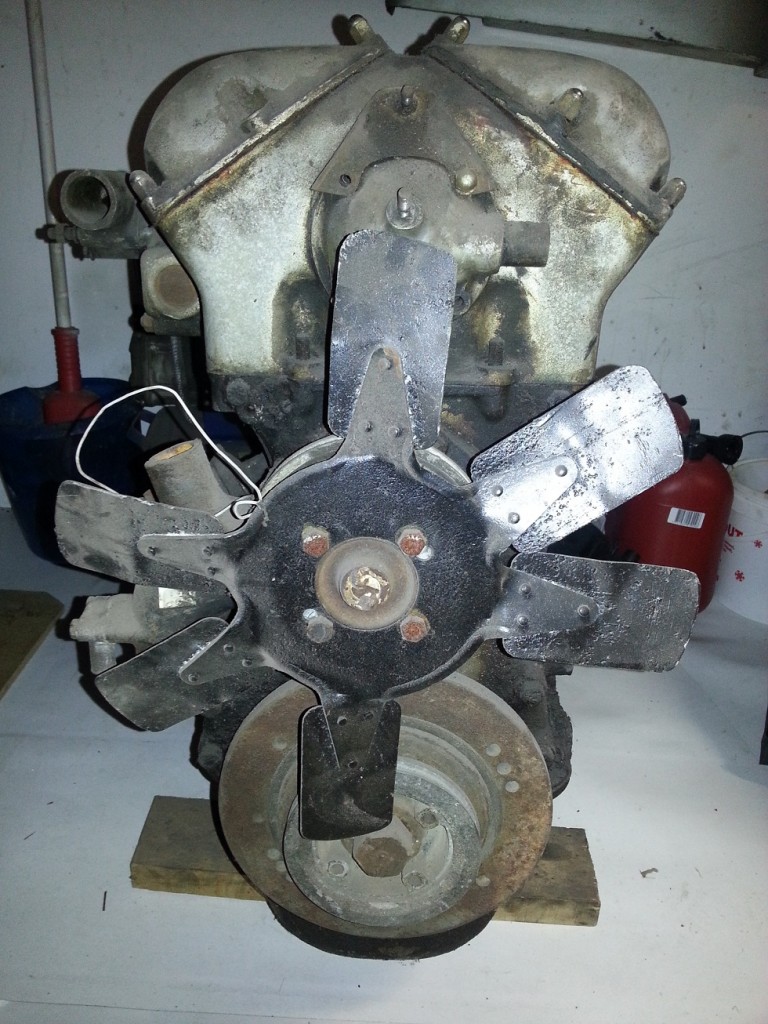
I started with the Xk140 block with the Xk120 head.EngineFrontDirty

The water pump, pulley and crankshaft damper are correct and can be reused for assembly of the original XK140 engine.

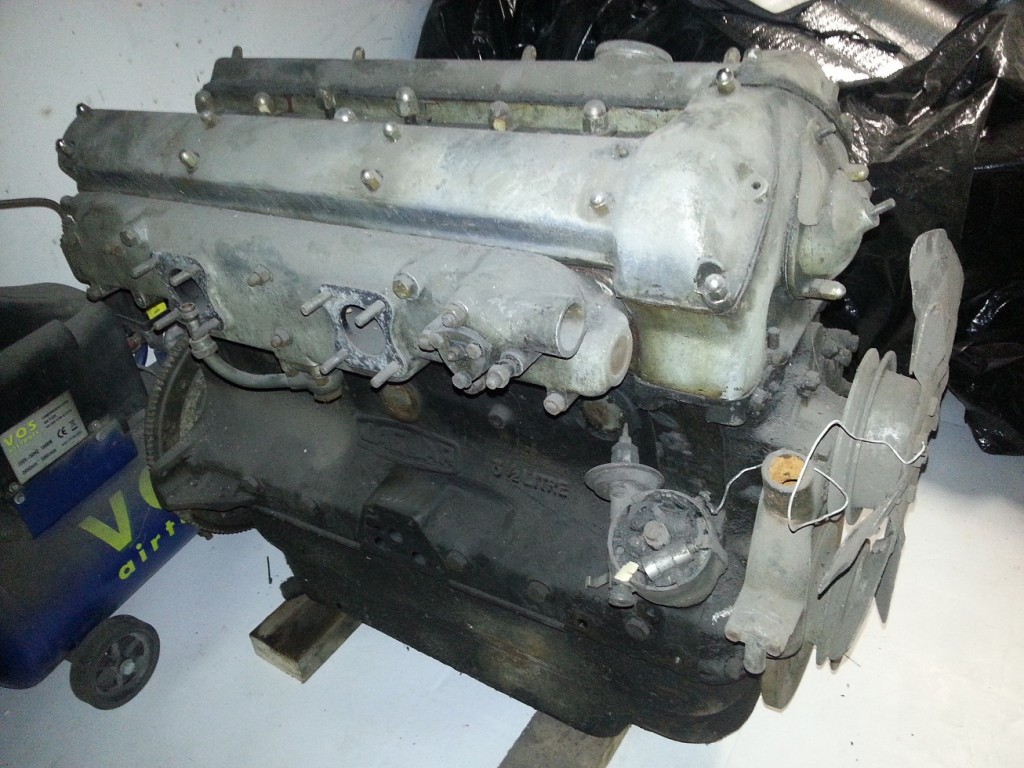
The Inlet manifold on the XK140 head was damaged by corrosion, but in the mean time I found a good replacement on the internet.

EngineInletDirty


The shown fan blades are suitable for a XK120 luckily the other engine has a XK140 fan blades mounted so that one will be used instead.

Both engines where not able to turn around freely, so the 46 years of sitting still, has not been good for the overall condition. Was the engine stalled at some time, there is only one way to find out.

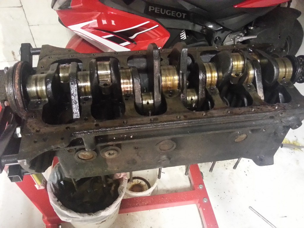
After removal of the oil sump the internals of the engine looked pretty normal. No broken crankshaft or broken connecting rods or other visible damage.

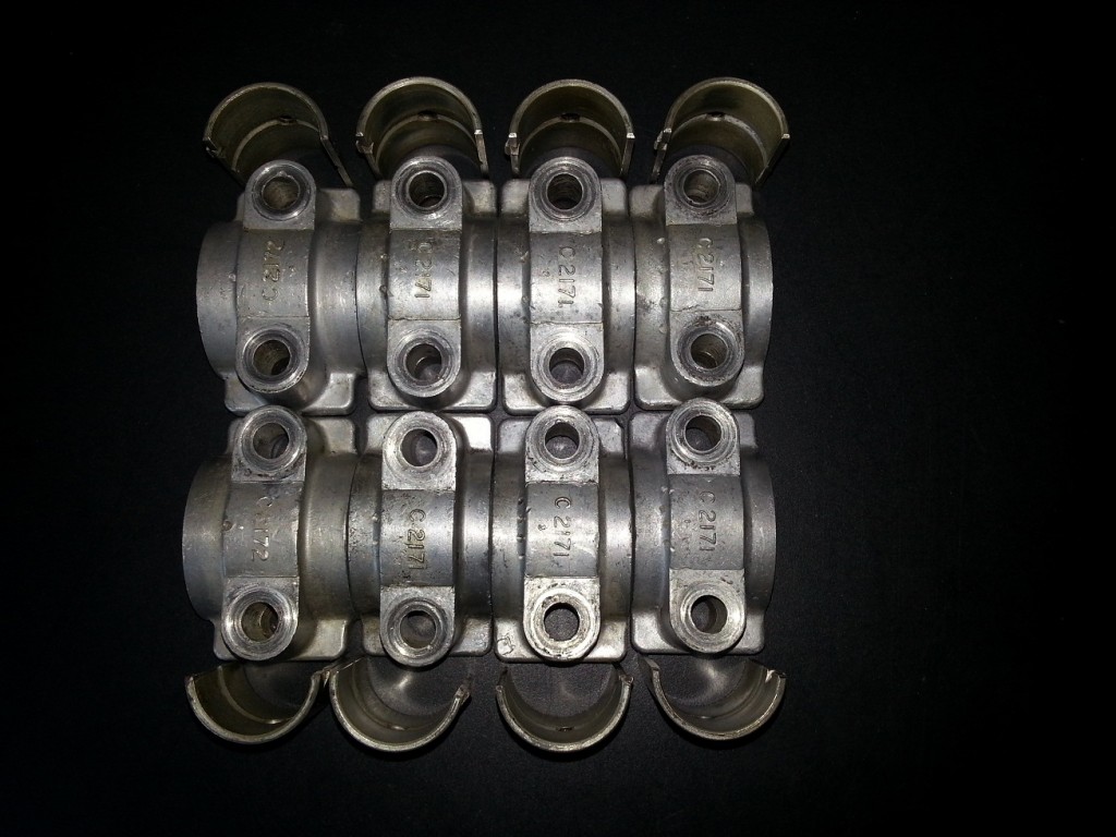
Remark: Label all bearing cap so they can be mounted on the exact same location and orientation. (In my case all caps where already marked with a unique id and number)

CrankshaftDirty

XK140 block without bearing caps


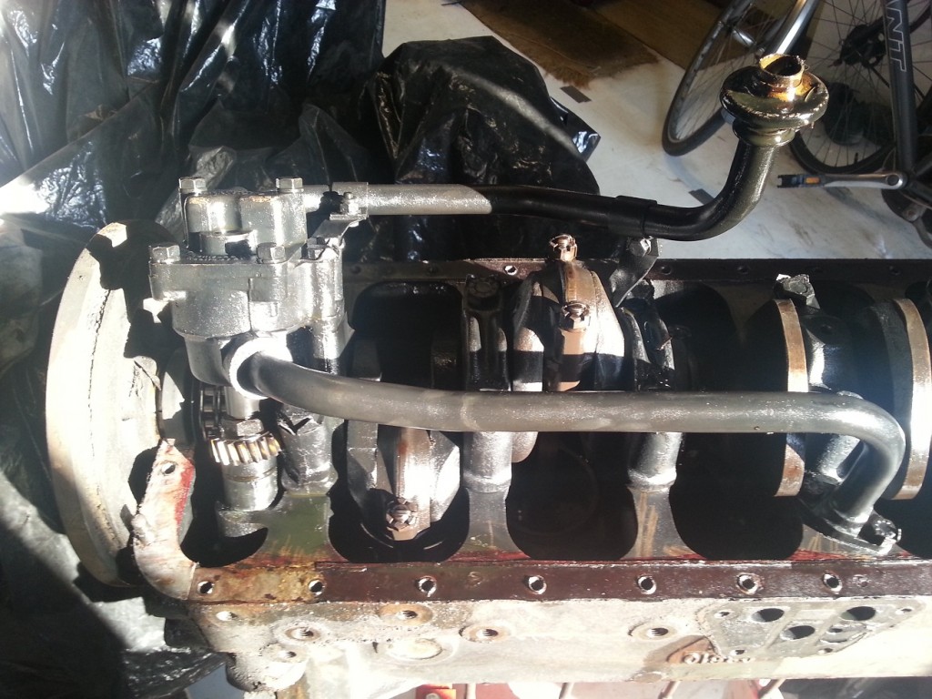
OilPumpDirty

Oil pump with connection pipes

After everything is disassembled and thoroughly cleaned I started with the the removal of cylinder head. Still searching for the cause of the not freely turning engine.

When the cylinders and pistons where visible, after the head was removed, it was all clear. Two cylinders where completely filled with lime, rust and dirt. After this was removed it was visible that one cylinder was badly damaged.
After measuring the diameter I found out that all cylinders where still standard with about 6/1000″ of wear.

Most probably the cylinder has to be drilled two sizes bigger +0.020 due to wear and corrosion damage.

Although the bearing caps has a unique id and number (stamped in the block and bearing caps) someone also made some unnecessary identification with a  center punch (one has been marked wrongly!).

CamShaftCapsCleanXk140

Cleaned cam shaft bearing caps


 Posted by at 19:54
mei 262014
 

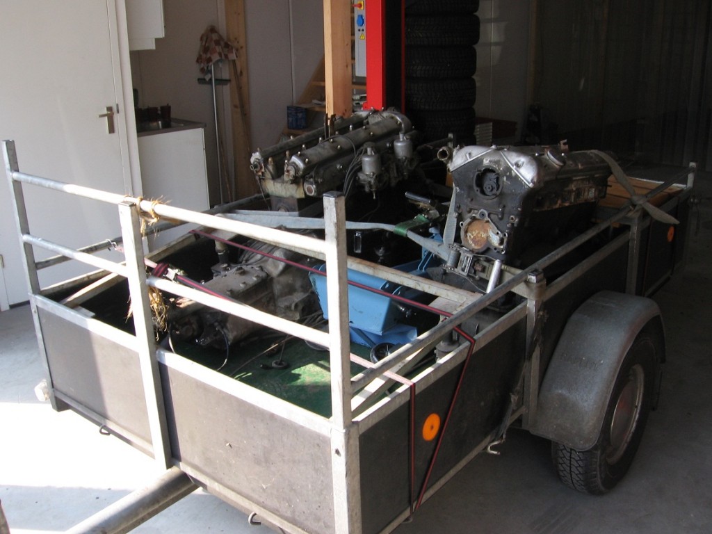
When I purchased the car, it was possible to buy a second spare engine.
The engine which belongs to the car consists of a XK120 block and XK140 head.
The spare engine consists of  a XK140 block and XK120 head.

To be able to build a complete XK140 engine I decided to buy the extra engine for Euro 750.

EnginesBuy


Engine 1:

  • Head G8877-7
  • Block W1800-8


Engine 2:

  • Head W7707-8
  • Block G9274-8S


Now after almost 5 year I started to disassemble both engines and found, due to 46 year of stagnation,  the following issues:

  • Sparkplug snapped of
  • Thread for sparkplug gone
  • Combustion-chambers damaged due to corrosion
  • Cylinder wear 
  • Pistons stuck in cilinder
  • Inlet and exhaust valves/seats damaged due to corrosion
  • Wrong type of camshafts mounted in the XK140 head (C13080 and C2444, required c5717 and c5718)

Hopefully it will be possible to combine the good parts from both engines and try to find the missing parts.

 Posted by at 20:10
jul 282013
 

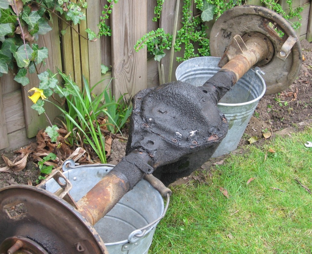
There rear axle was the most difficult part to dissemble until now.
To remove the hubs from the rear axles an enormous amount of brute force is needed (8 a 10 tons). After trying different type of pullers I managed to remove them.
One Hub was damaged and need to replaced. Lucky enough I found a good set of rear hubs in the US via ebay for only 53 euro (including shipping costs).

RearAxleOld

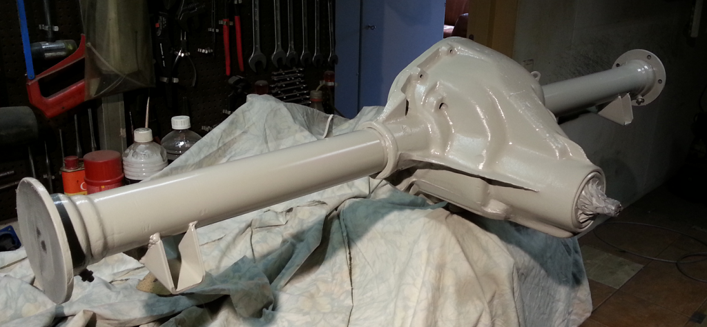
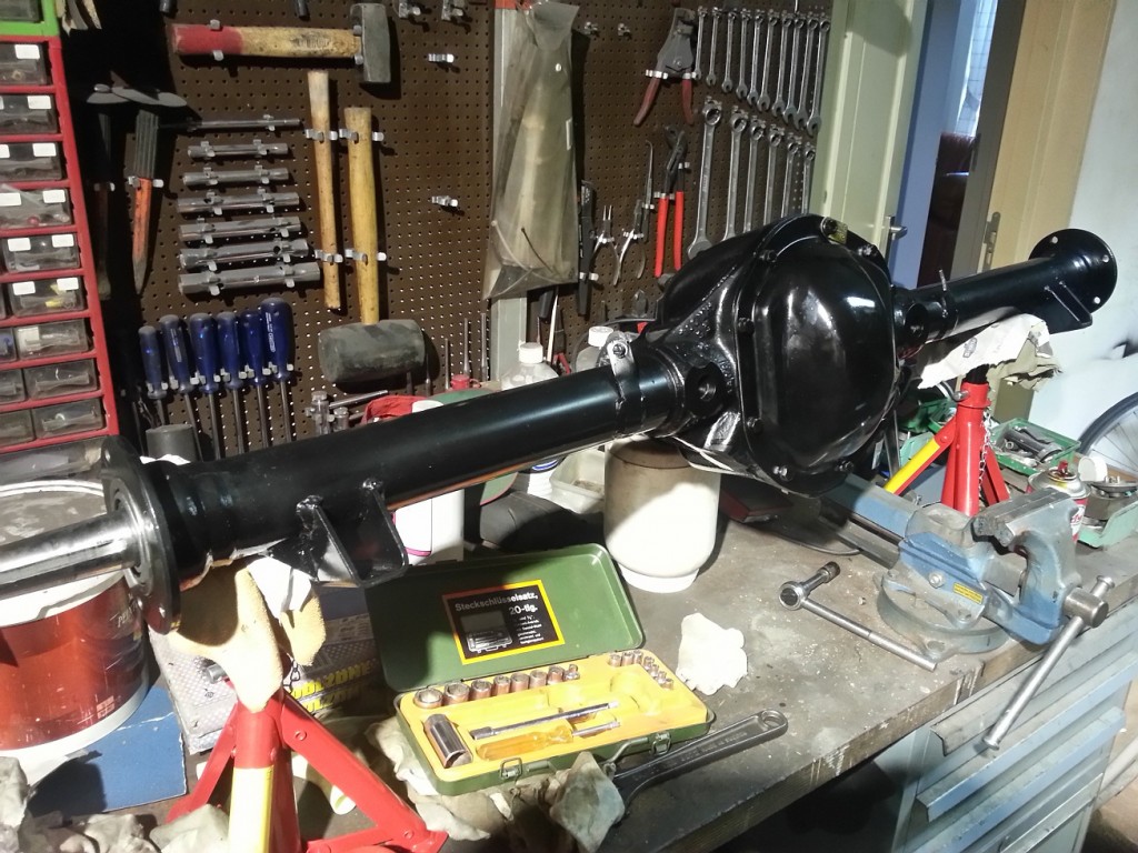
After removing all dirt and grease I painted the rear axle in epoxy primer and 2 layers of gloss black paint. After several weeks of dry time I could start to re-assemble everything.

RearAxlePainted

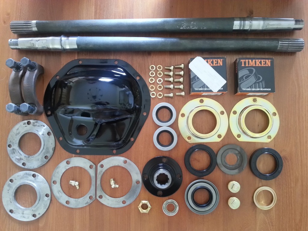
My first idea was to replace all bearings inside the rear axle, but after gathering information by several Jaguar specialists, I decided to replace only the left and right wheel bearing in the rear axle. (The pion-and crown wheel bearings are not replaced often) All oil seals are of course replace with new ones.

RearAxlePartsAll seperate parts needed to rebuild the rear axle

For removing the old bearing and mounting the new one’s I used the home made Hydrolic Press (See special tools). Incredible how much force is needed to replace these bearings (approximately 8 to 10 tons)
After mounting all separate parts the rear axle looks factory fresh again.

RearAxleNew2

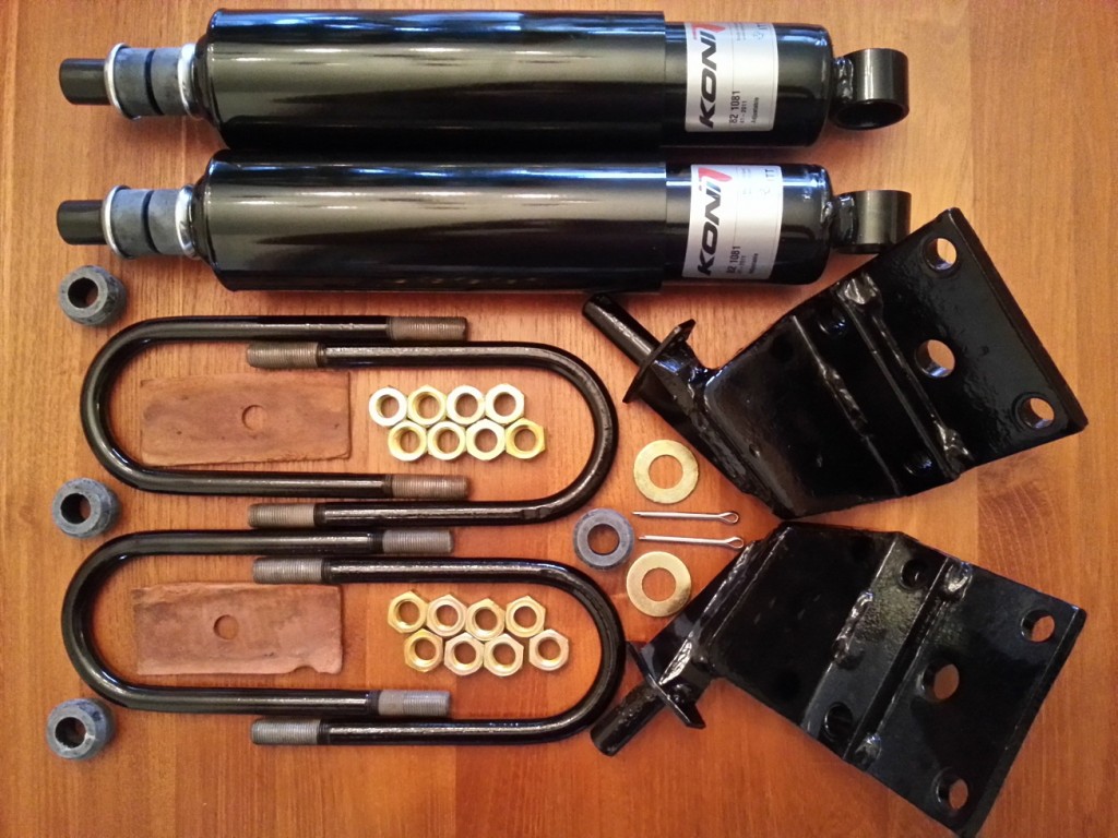
After the rear axle is lifted on top of the rear leave springs the can be mounted, including the rear shock absorbers.

ReartShockAbsorberPartsAll seperate parts needed to mount the rear axle on to the leave springs

 Posted by at 16:27
mei 192013
 

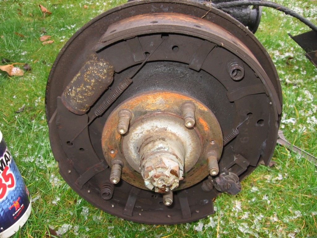
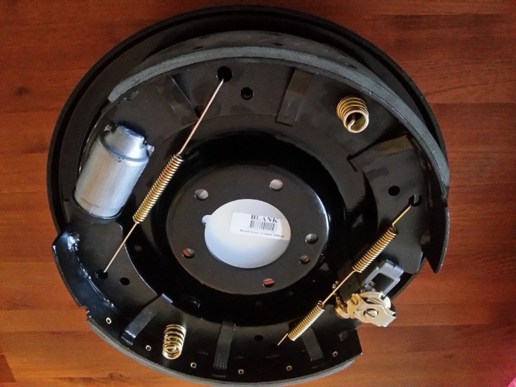
Both rear brakes has undergone a complete refurbishment. Now they look and hopefully brake as new again.

Read Brakes OldRear Brakes New


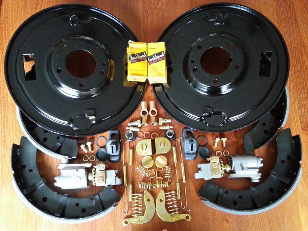
The above transformation has been made possible with all separate parts shown on the following picture

Rear Brakes Parts

All seperate parts needed to rebuild the rear brakes


 Posted by at 20:30