aug 142015
 

My first idea was to leave the clutch unit unrestored, because there was still some original paint available and he did’t look so bad. After inspection I saw a lot of rust inside (Springs and clutch plate) and therefore decided to restore the clutch unit as well.

ClutchUnitOriginal

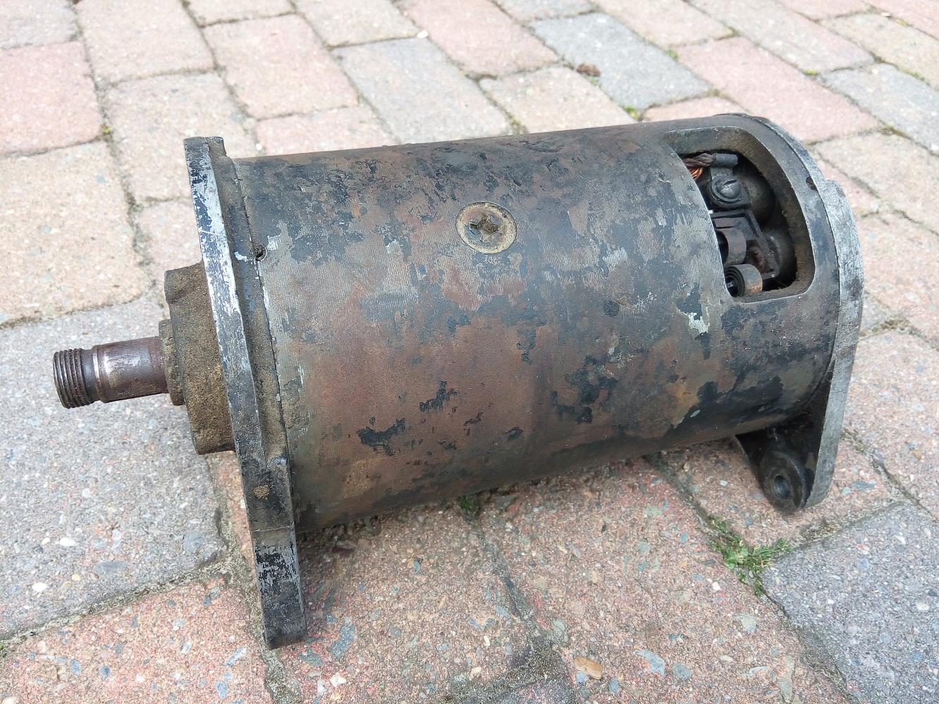
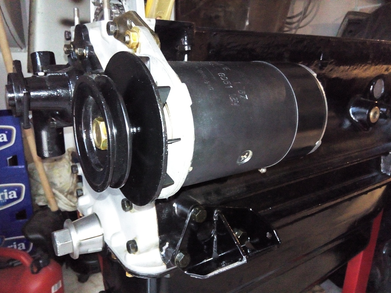
The original clutch unit which was mounted on the flywheel

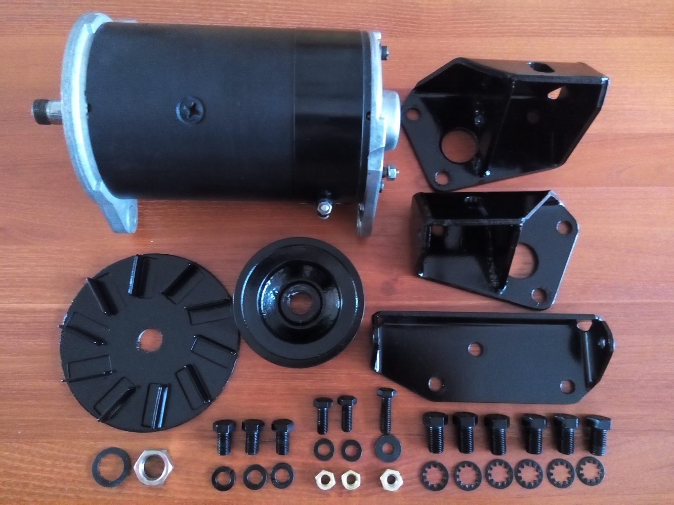
So first I disassembled everything (be careful with removing the three nuts, there is a lot of pressure due to the twelve strong springs). Cleaned everything with glass bead blasting and sprayed everything with a new fresh layer of paint. I used special paint for the parts who can become very hot (< 800℃)

NewPartsClutchUnit

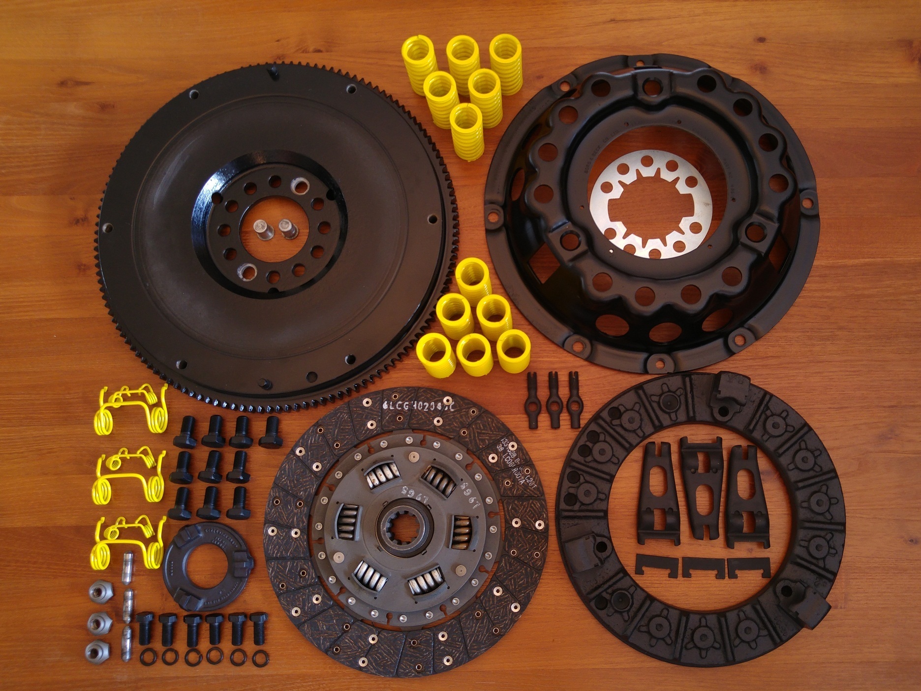
The original paint on the springs, who will deliver the pressure to the clutch plates, where  not visible anymore. But in the documentation is stated the they should be painted yellow.

ClutchUnitFinished

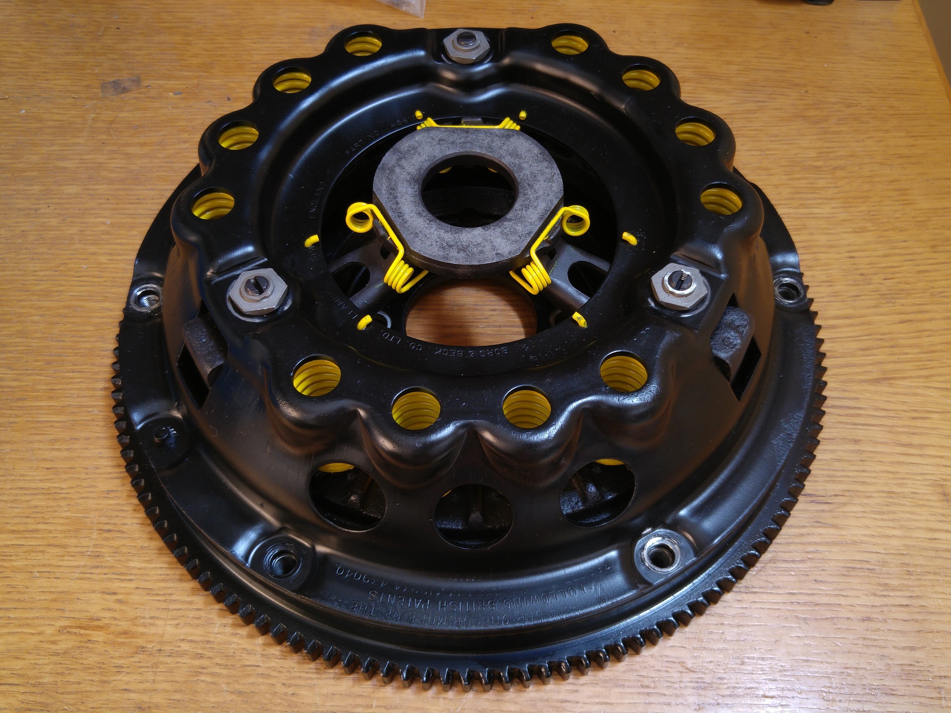
The restored clutch unit, ready to be mounted

I didn’t know if it was really necessarily but I placed the cover on the same location as it was originally. During the assembly I noticed that the pressure plate has been balanced in some way (In the second picture you can obvious the have drilled 7 extra holes to remove some material).

 Posted by at 14:11
mei 172015
 

MotorOrigineel

Front side of the engine with wrong fan blade

Originally the engine inside my car was equipped with the wrong type of fan blade. Instead of the xk140 type blade (symetric) it was equipped with the xk120 fan blade (a-symatric)

CoolingFanParts

All parts needed to rebuild the fan blade installation

With the fan blade mounted the front of the engine is now almost finished. Only the cylinder head is missing, which is still at the machinery.

It is not completely clear if the aluminium blades should be painted black or not, the documentation is not very consistent. Most original pictures/photos show the bare aluminium without any paint.

CoolingFanMounted

 Posted by at 12:54
feb 222015
 

Before assembly of the engine could start all bearings are measured:

  • Mains bearings (6/100, still within specification)
    To prevent honing the crankshaft(I can only be done twice, and it will get less riged) I accept the play as it is.
  • Thrust washers (with one STD and one oversize 11/100)
  • Big-end bearings (4/100, still within specification)
  • Small-end bearing (No notable play)
CrankshaftDirty

Original uncleaned bottom view of the crankshaft

All separate parts are thoroughly cleaned and the following parts are bought new:

  • New main bearings (STD)
  • New big-end bearings (STD)
  • New thrust washers (STD + oversize)
  • New piston set (complete with 4 rings, gudgeon pin and circlips)
Crank Shaft parts

All cleaned and new parts needed to mount the crank shaft and pistons

Remarks:

  • Don’t forget the oil sealing ring at the rear block before the crankshaft is mounted.
  • Mount the bearing so the indicators will match (they are all numbered and the engine block also has these numbers stamped into the casting) Numbers should be kept at the inlet side.
  • The pistons are number from 1 until 6 starting from the backside of the block
  • The piston numbers are stamped into the connection rod and the big-end bearing cap
  • The piston numbers should be readable from the exhaust side
  • The compression piston rings should be mounted in opposite direction 0 and 180 degrees. I also mounted the oil scrapper rings at 90 and 270 degrees.
  • When piston 1 and 6 are in the TDC position the distributor shaft Distributor Shaft Positionshould be positioned at 5 to 5. The distributor shaft will make a half rotation when the crankshaft has made one.
  • When the timing chain is connected to camshaft make sure the distributor shaft is positioned as shown on the picture.
    (Remark the notch is positioned left from the middle at 5 to 5)

Because I found some pictures, original made in jaguar factory with painted text, I painted the “Jaguar” logo and the text “3 1/2 litre” in white.
Bellow the engine block with the pistons and crankshaft completely mounted.

hdr

Engine with the crankshaft and pistons installed

CrankShaftFinished

Crankshaft, bearing caps and connecting rods installed 

 Posted by at 17:42
apr 142016
 

Because not all parts needed for the cylinder head, inclusive the inlet – exhaust manifolds fit into one photo, I made three photo’s.

CylinderHeadParts

All parts needed to finish and mount the cylinder head on the engine

ExhaustManifoldParts

All parts needed to mount the exhaust manifolds

InletManifoldParts

All parts needed to mount the inlet manifold

All parts needed to rebuild the breather housing

Now that the cylinder head and exhaust manifolds are mounted it already begin to look at a complete Jaguar XK engine. The exhaust manifolds are bought via ebay in the USA for only $50 (inclusive national shipping ) A friend of the neighbors was kindly enough to take them for me to the Netherlands. Because the enamel still looks like new so I assume that the previous owner has redone this in the past.

CylinderHeadMounted

Cylinder head and exhaust manifold mounted

EngineFinishedRight

Cylinder head and inlet manifold mounted

 Posted by at 18:20
mei 172015


DynamoOrigineel

Original dynamo removed from engine

Because the above dynamo, mounted to my engine, was originally from a XK120 I needed to look for the correct one.

This dynamo has a brass identification plate with the following information:
Lucas 22452B, GC51, C45PVS/5, 12V, 53

The dynamo I needed should have the following numbers:
Lucas ,22462B, GC51, C45PVS/5, 12V, 56

An other XK140 restorer in my neighborhood offered me a deal I couldn’t refused.
Exchange mine xk120 dynamo for a correct, fully restored, xk140 dynamo and give him a small reimbursement for the parts he used for the restoration.

DynamoParts

All parts needed for rebuilding the dynamo

All separate parts are again sandblasted and pained black so they all look again as new.
To prevent rust, and make it easier to remove them in the future, the bolts are also painted black and mounted with a little bit tectyle.

DynamoMounted

Dynamo and engine brackets mounted on the engine

 Posted by at 14:05
nov 302014
 

After I received the engine block from the revision company I started to remove all external rust. The dirt and crease was already removed before it went to this company. The outside of the block can now be sprayed with special engine paint (MOTIP engine paint black gloss) which can withstand 150 degrees.

Engine Painted

Due to experience from other XK restorers (replaced freeze plugs came loose) I decided to leave the freeze plug in place because they still look and feel very thick (it was not possible to make dents in them with a hammer). On the original block there where also no signs of leakage. The plugs didn’t show any damage/rust when inspected from the inside (via water channels)

The basis for the engine block is now finished and we can start with the following items (which will be handle in separate parts):

 Posted by at 16:08
jul 022014
 

Cilinder Head

After all valves where removed and cleaned it was clear, that from the to heads (24 valves), a good set of valves could be combined. Some of the valves show corrosion damaged and can’t be used anymore. The corrosion in the water ports are not to bad and can be left as they are now.

CilinderHeadTop

CilinderHeadBottomCilinderHeadNumber
One tappet guide should be replaced because it is cracked (became visible  after cleaning)

Because one of the mounted camshafts (outlet) where from a XK120 (less valve lift) I bought an other one from a jaguar MK2 (C13081) Together with the mounted inlet valve is C13080 we have a matched set again.

Cilinder Block

After removing all main bearings and the crankshaft we could start removing the pistons.
Because the block has not be moved for over 46 years this was not a easy job. The first three pistons could be removed quite easily but the last three where deadlocked. After I applied penetrating oil and wait a couple of weeks, I managed to knock them one by one loose with a block of wood and a heavy hammer.

One of the six cylinder walls was badly damaged by corrosion.

All parts needed to rebuild the head and block are thoroughly cleaned and sorted, ready for the machinery.

 Posted by at 11:53
jun 102014
 

I started with the Xk140 block with the Xk120 head.EngineFrontDirty

The water pump, pulley and crankshaft damper are correct and can be reused for assembly of the original XK140 engine.

The Inlet manifold on the XK140 head was damaged by corrosion, but in the mean time I found a good replacement on the internet.

EngineInletDirty


The shown fan blades are suitable for a XK120 luckily the other engine has a XK140 fan blades mounted so that one will be used instead.

Both engines where not able to turn around freely, so the 46 years of sitting still, has not been good for the overall condition. Was the engine stalled at some time, there is only one way to find out.

After removal of the oil sump the internals of the engine looked pretty normal. No broken crankshaft or broken connecting rods or other visible damage.

Remark: Label all bearing cap so they can be mounted on the exact same location and orientation. (In my case all caps where already marked with a unique id and number)

CrankshaftDirty

XK140 block without bearing caps


OilPumpDirty

Oil pump with connection pipes

After everything is disassembled and thoroughly cleaned I started with the the removal of cylinder head. Still searching for the cause of the not freely turning engine.

When the cylinders and pistons where visible, after the head was removed, it was all clear. Two cylinders where completely filled with lime, rust and dirt. After this was removed it was visible that one cylinder was badly damaged.
After measuring the diameter I found out that all cylinders where still standard with about 6/1000″ of wear.

Most probably the cylinder has to be drilled two sizes bigger +0.020 due to wear and corrosion damage.

Although the bearing caps has a unique id and number (stamped in the block and bearing caps) someone also made some unnecessary identification with a  center punch (one has been marked wrongly!).

CamShaftCapsCleanXk140

Cleaned cam shaft bearing caps


 Posted by at 19:54
aug 292014
 

Today I brought the cylinder-head and cylinder-block to “Rombouts revisie” in goirle.

The measured clearance:

  • Crankshaft STD with 15/100 mm clearance
  • Inlet Camshaft STD with no visible play
  • Outlet Camshaft STD with no visible play
  • Piston 1 STD with 15/100 mm clearance
  • Piston 2 STD with 15/100 mm clearance
  • Piston 3 STD with 15/100 mm clearance
  • Piston 4 STD with 15/100 mm clearance
  • Piston 5 STD with 15/100 mm clearance (after drilling to 75/100 mm still corrosion visable)
  • Piston 6 STD with 25/100 mm clearance (after drilling to 50/100 mm still corrosion visable)
  • To match play on the valve guides
  • Valve seats are worn and will be replaced by unleaded fuel types

.010″ = 10/1000″ = 0,25 mm = 25/100 mm
.020″ = 20/1000″ = 0,50 mm = 50/100 mm

Engine Drilling Machinery Engine Drilling Detail

Before the actual revision started they executed a cylinder head water pressure test to discover possible water leakage. (Due to the visible corrosion in the cylinder head) The conclusion was that it already started to leak inside combustion chamber 5 at a very low water pressure level. The advise was to look for a different cylinder head due to the high corrosion level in combustion chamber 4, 5 and 6. So I brought my XK120 head for the same test and although the water channels where no so good, the combustion chambers where much much better. Because the head between the XK120 and XK140 are technically equal (except for the number stamped into the casting) I decided to take the XK120 head.

The valves from both heads (24 in total) are not usable anymore because;

  • 10 pieces are damaged by corrosion
  • 7 pieces are shortened to compensate the excessive valve seat wear.

Work for the revision company:

  • Re-sleeve cylinder wall 5 and 6
  • Drill all cylinders to +020
  • Flattening of the cylinder block
  • Water pressure tests on two different XK cylinder heads
  • Replace all valve seats with unleaded fuel types
  • Replace all valve guides
  • Flattening of the cylinder head
  • Welding all damaged water channels in the cylinder head (12 x)
    The discoloring around the water channels shows what has been welded

Cylinderhead Detail Cylinderhead

In the mean time I ordered the following new parts:

  • 6 Pistons oversize +20
  • 6 inlet valves
  • 6 exhaust valves
  • Crankshaft bearing
  • Thrust bearing
  • Big end bearings
  • Camshaft bearing
  • Bottom gasket set (including oil seals)
  • Top gasket set (including oil seals)

All preparation has been finished (10 october 2014), the assembly process can now be started.

 Posted by at 14:13
mei 262014
 

When I purchased the car, it was possible to buy a second spare engine.
The engine which belongs to the car consists of a XK120 block and XK140 head.
The spare engine consists of  a XK140 block and XK120 head.

To be able to build a complete XK140 engine I decided to buy the extra engine for Euro 750.

EnginesBuy


Engine 1:

  • Head G8877-7
  • Block W1800-8


Engine 2:

  • Head W7707-8
  • Block G9274-8S


Now after almost 5 year I started to disassemble both engines and found, due to 46 year of stagnation,  the following issues:

  • Sparkplug snapped of
  • Thread for sparkplug gone
  • Combustion-chambers damaged due to corrosion
  • Cylinder wear 
  • Pistons stuck in cilinder
  • Inlet and exhaust valves/seats damaged due to corrosion
  • Wrong type of camshafts mounted in the XK140 head (C13080 and C2444, required c5717 and c5718)

Hopefully it will be possible to combine the good parts from both engines and try to find the missing parts.

 Posted by at 20:10