okt 152017
 

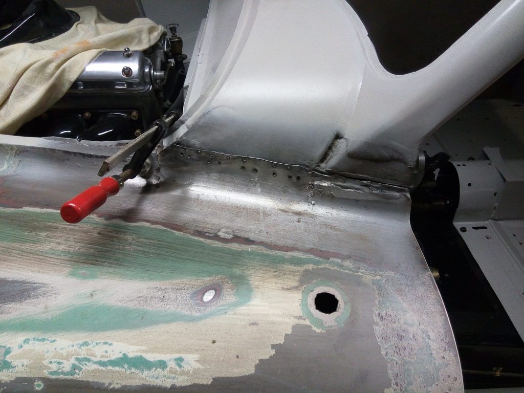
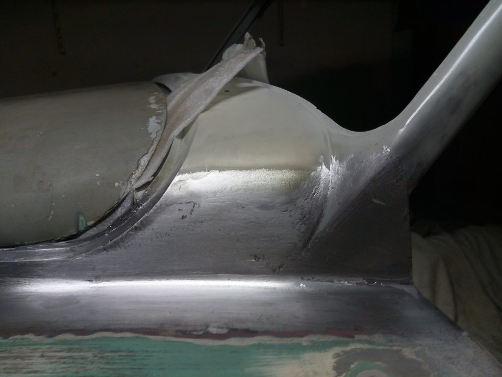
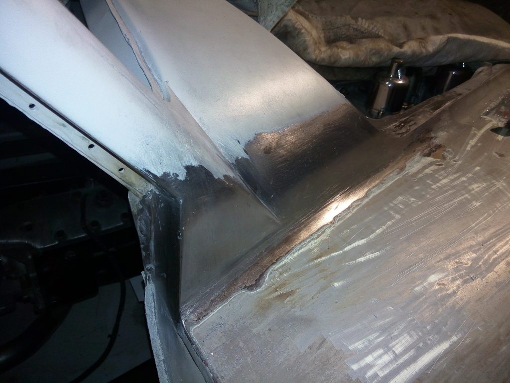
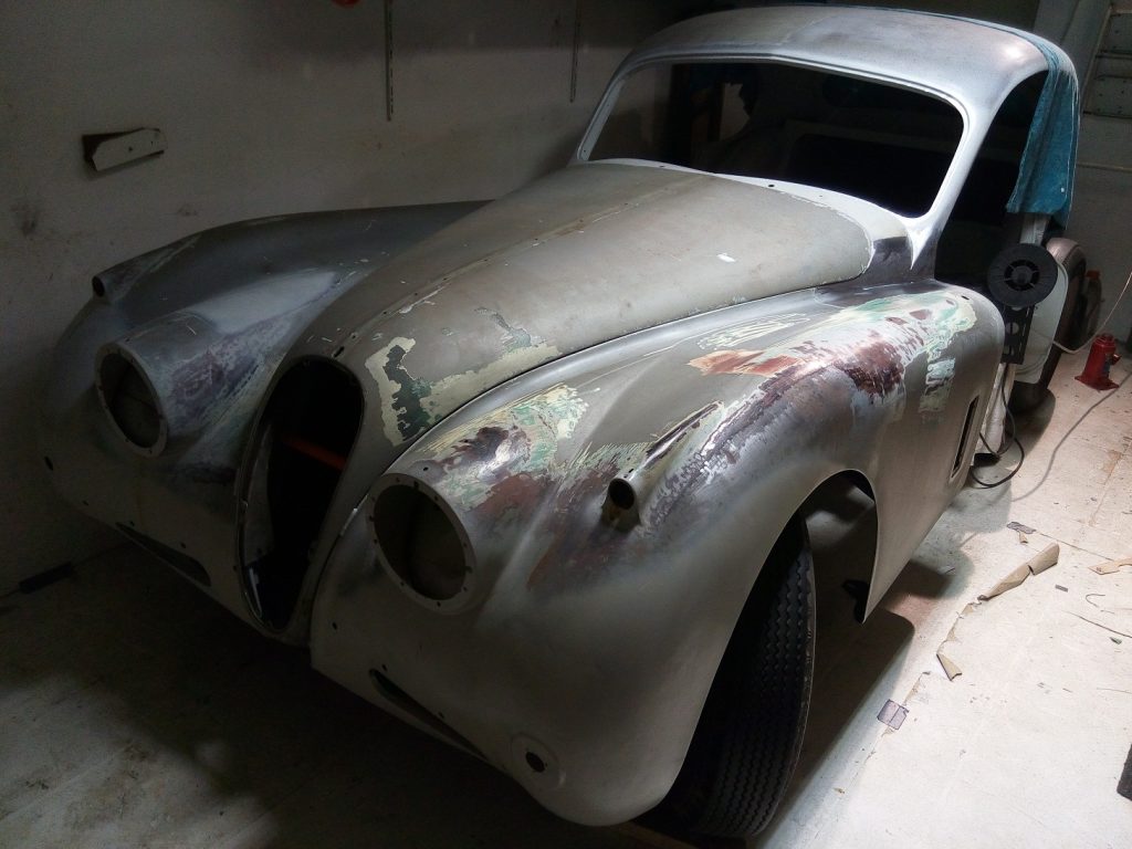
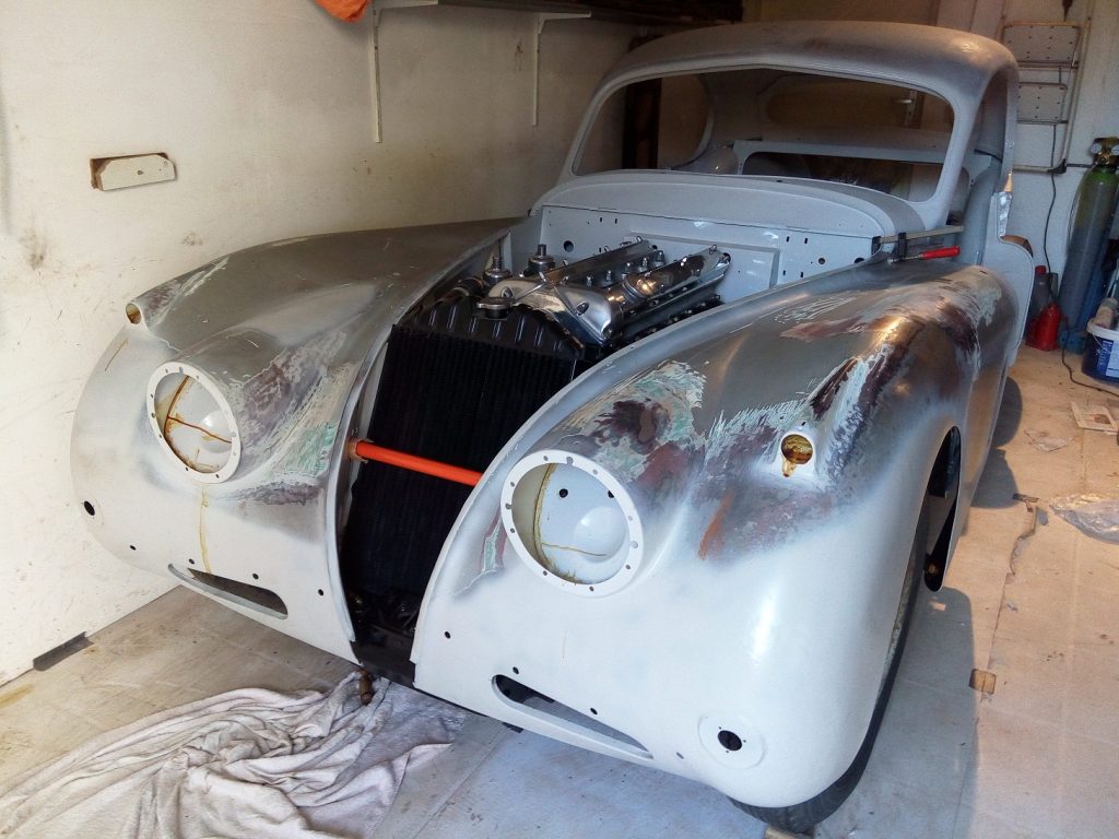
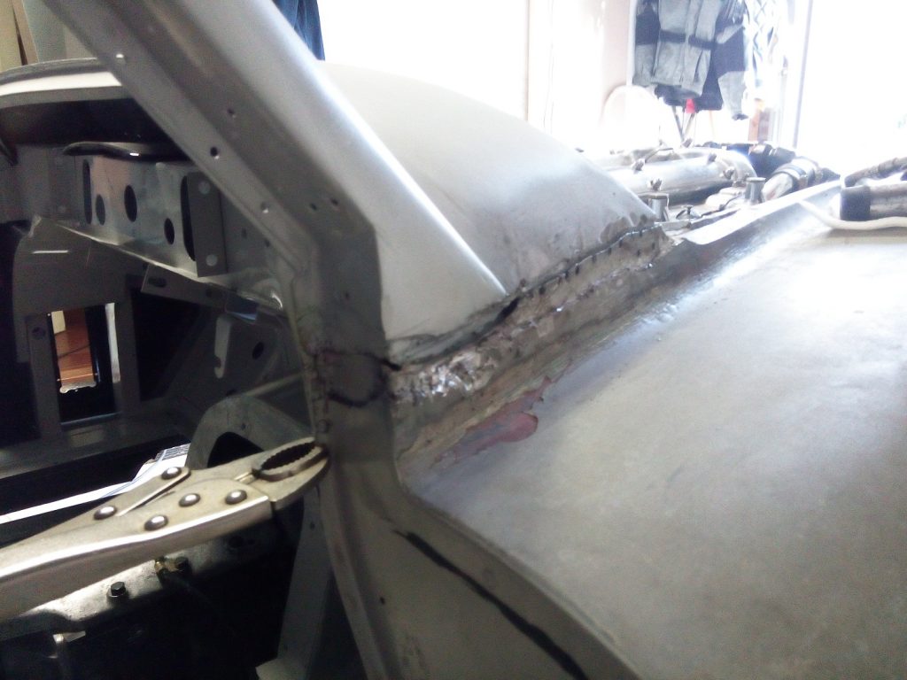
Now the left and right front wings are restored, and the inside has been painted, it is time to place them back onto the body. Although most restorers leave them onto the body en remove the lower part of the front wings to repair the dashside strengtheners, I decided to remove the whole front wings at the place the where originally fixed to the body.

This method has the following advantages/disadvantages:

  • + Removing and mounting can be done by myself.
  • + Cleaning the inside of the front wings is much easier.
  • + Repair and cleaning of the dashside strengtheners is very easy
  • + Afterwards it will be invisible to see they where removed.
  • + During the restoration process it was easier to store them temporarily in the attic.
  • –  Difficult to place the wings back on exact the same spot.
  • –  Lead must be placed back, which can be difficult.

The front wings are welded to the body nearby the front windscreen. Nearby the radiator the front wings are mounted on three places with bolts onto the chassis.

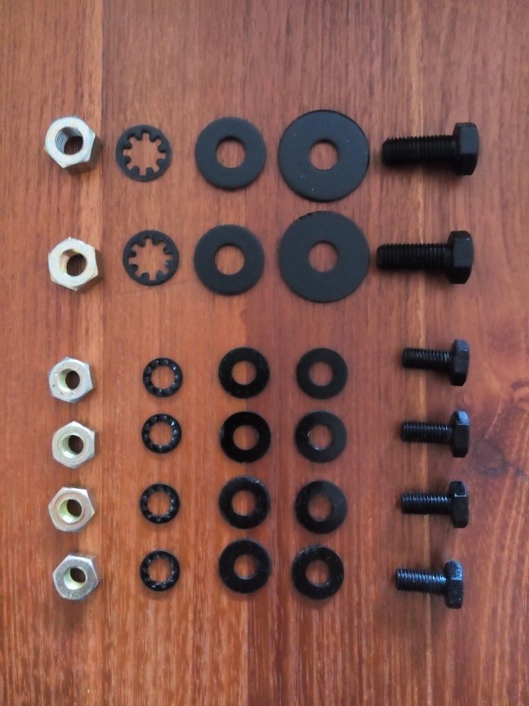
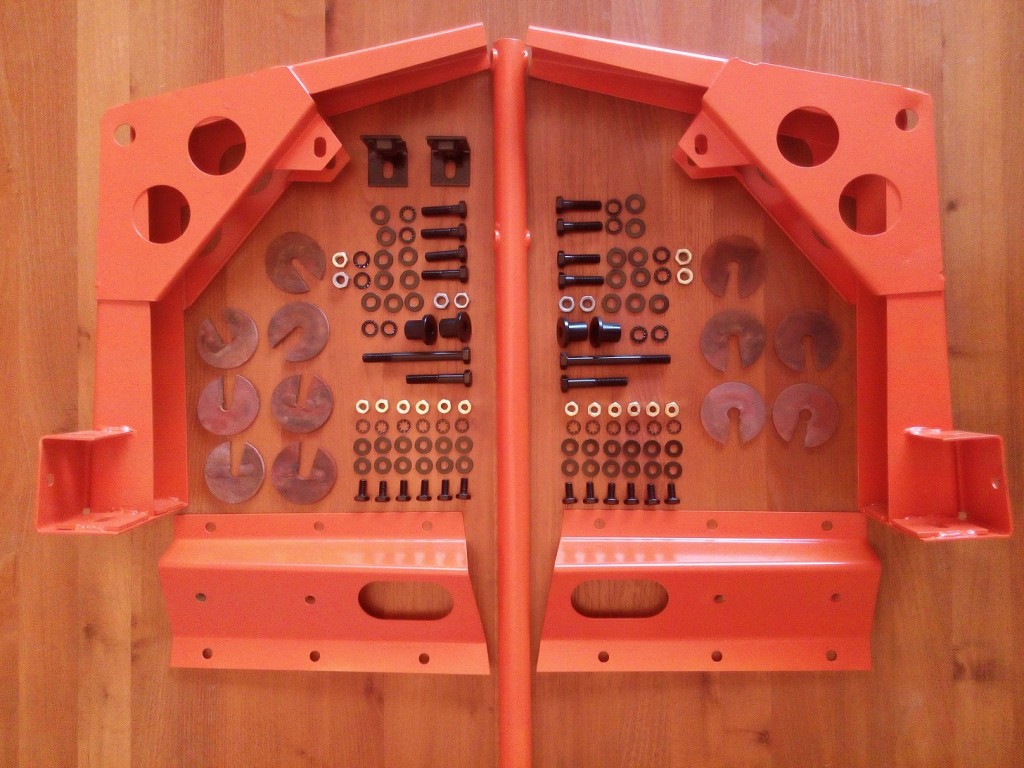
Parts needed to bold the front wings onto the chassis

Now that the front wings are mounted and the front hood is placed, it starts to get the contours of a Jaguar xk140 again.
 Posted by at 14:51
aug 102016
 

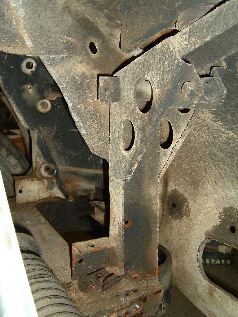
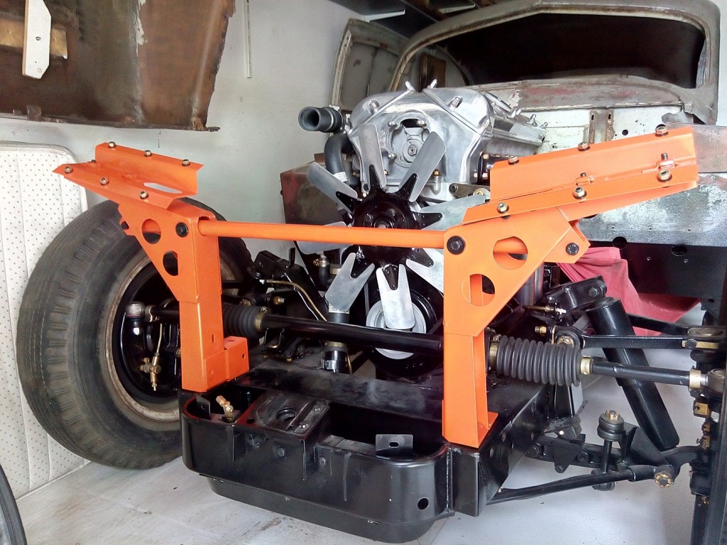
The front wing supports are used for the following purposes;

  • Keeps the the front wings on the right place in front og the car
  • Mounting of the radiator
FrontWingSupportOrg

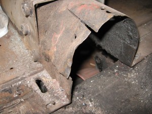
Original front wing support on the right side

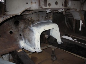
The front wing supports are only painted in some sort of orange undercoat, as can be seen on the original photo above. The complete body was leveled out in the factory with aluminium or plastic(kautex) distance pieces. (See dish shaped parts in the next photo)

FrontWingSupportParts

Front wing support parts

On the right side we also have to mount two mounting brackets which are used for fixing the distributor shield.

hdr

Front wing support mounted on the body

The tie bar which connect the two front wing supports with each other must be removed when the front wings are mounted. The tie bar is running through the front wings and there must be mounted when bot front wings are in place. (See original photo)

 Posted by at 14:31
mei 172016
 

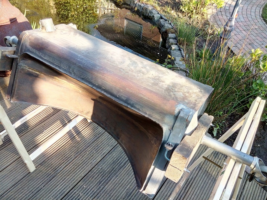
After I bought the car I discovered that the fuel tank was missing. This proves that, even for a big part as a fuel tank, as already mentioned earlier, it is very difficult to see a car is complete.

A friend of mine, also the owner of a XK140 FHC, has one extra fuel tank in his pile of car parts. This tank is original but has two small issues:

  • Small dent in the underside of the tank nearby the filter element
  • Small hole just underneath the mounting bracket (grey area on the right side)

To make the cleaning and sealing process more convenient, I connected two extension on which the tank can turn freely.

hdr

Fuel tank during the internal cleaning process

After both issues where solved the tank is ready for the internal cleaning and coating in the following steps.

  • Turn the fuel tank, backwards and forwards, filled with small sharp stones
  • Rinse thoroughly  with clean water to remove dust residue.
  • Fill the fuel tank with “Metal Prep 1/4 gallon” from POR15 and rotate the tank for one hour.
  • Remove the Metal Prep remaining and rinse thoroughly  with clean water to remove. (I used a pressure washer)
  • Let the tank dry completely (Outside in the sun)
  • Fill the fuel tank with  “Fuel Tank Sealer 1/4 gallon” from POR15 and rotate the tank for one hour.
  • Drain the fuel tank for one hour to remove excess sealer from the tank.
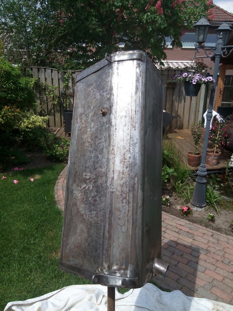
TankCleaned

Tank after removing the rust on the outside

With sandpaper the outside of the tank is cleaned and prepared for painting.

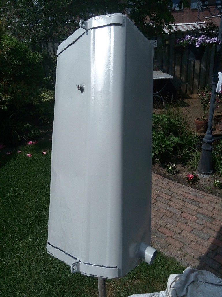
TankSealed

Fuel tank painted and seams sealer aplied

After the tank is painted (epoxy primer) the outside seams are sealed (3M body sealer).
Now the “Body shuts spray” from 3M can be aplied. To be able to clean the tank easily a last layer of satin black paint is applied.

hdr

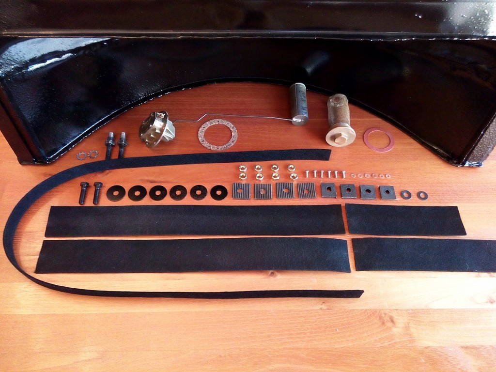
All fuel tank parts needed for rebuilding and mounting

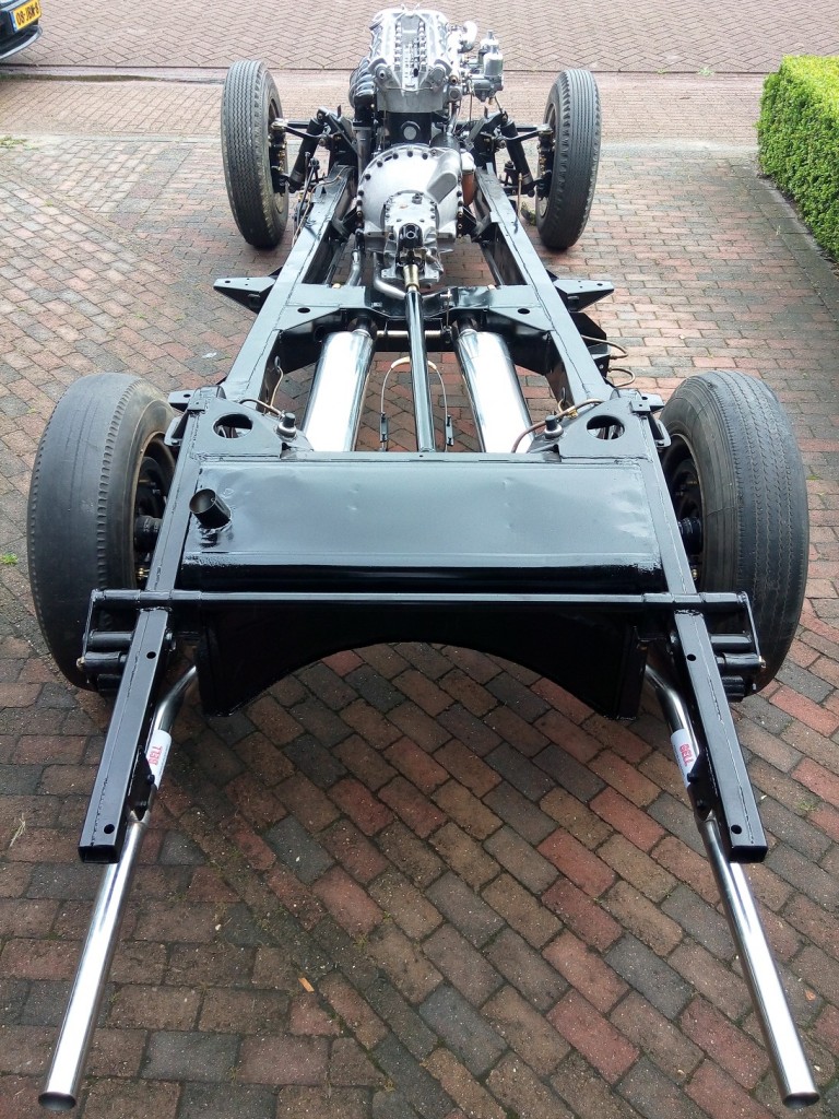
Now only the felt must be mounted (On the fuel tank and the chassis) and the rolling chassis is almost finished.

FuelTankFinished

Fuel tank mounted onto the chassis 

 Posted by at 21:16
dec 202014
 

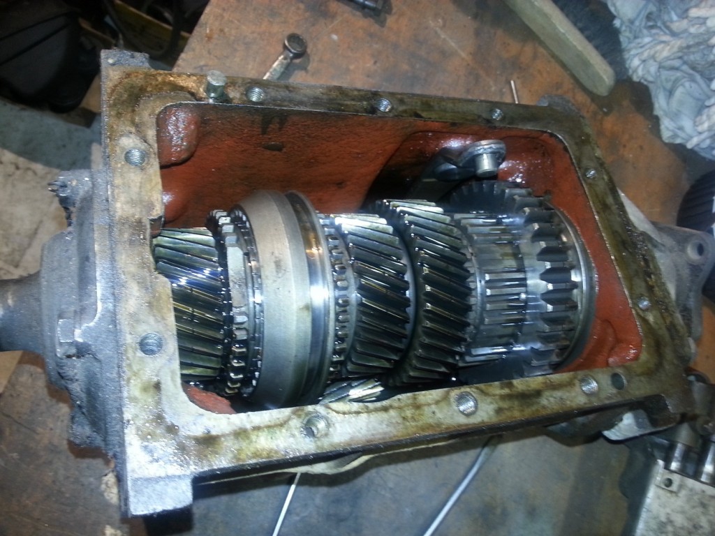
GearboxInternalAfter removing the gearbox cover I was pleased to see that there was still 0,5 liter of oil inside. All the gears looks still great.

The bearing of the incoming axle was blocked for some reason but I already planned to replace all bearing anyway.

The needles bearings where also not so good but the bearing surface was still in good shape.

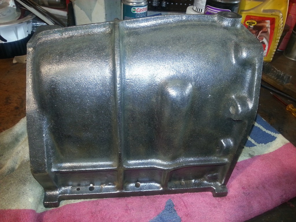
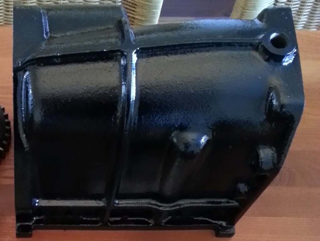
After all internals where cleaned, checked and stored I started with cleaning the gearbox cover.

I will leave the gearbox cover as it is for the time being. I don’t want to disassemble to much at the same time be able to assemble everything as it should.

Gearbox Cleaned Gearbox Painted


After the outside gearbox cover was decreased and all rust removed, it could be painted epoxy primer and several layers of black paint.

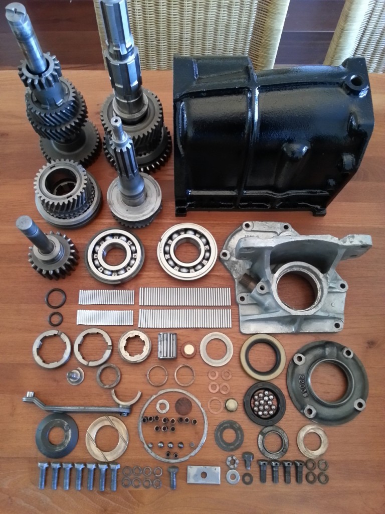
Gearbox Parts

All separate parts used to rebuild the gearbox without cover

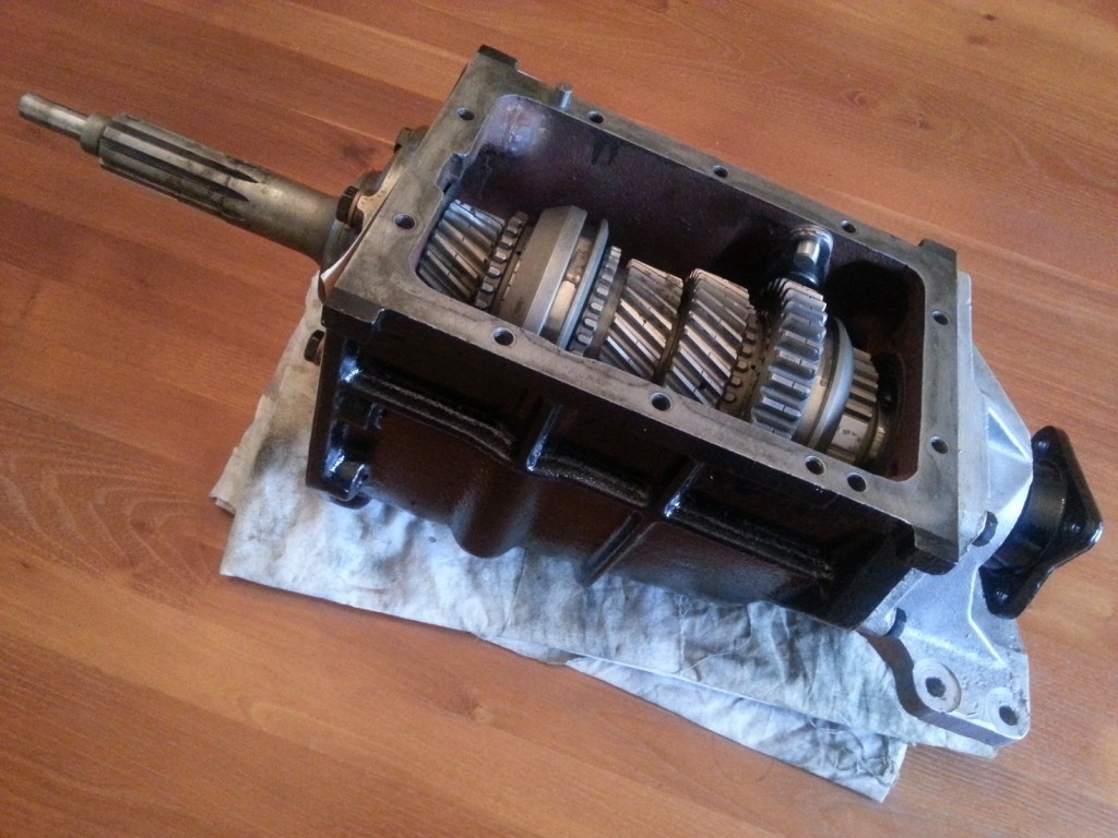
GearboxInternalFinished

Gearbox (without cover) mounted


 Posted by at 17:27
aug 032009
 

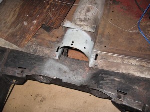
Before I could start with fitting the gearbox cover the bulkhead and driveshaft tunnel needs to be fixed.
For some reason it looked like they have removed the gearbox from the car compartment, and needed some extra room. They used a chisel to open up the bulkhead and drive shaft tunnel for about 4 inch.

BulkheadBeforeBulkheadAfter
TunnelBeforeTunnelAfter
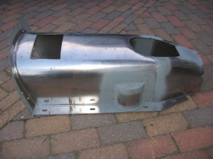
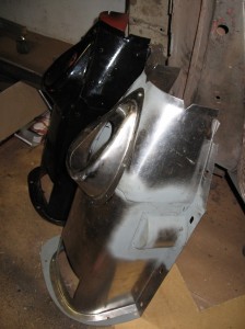
I had to reproduce or buy a gearbox cover because this part was not available anymore. Buying one on the internet is very expensive (used or new) so I decided to make one myself from the sheet metal left from the other jobs.

In the direct neighborhood of my home there is a jaguar garage situated and I could borough one from them. It was a cover from a XK150 but they should be interchangeable and could be used as an example.

GearboxCover1GearboxCover2

 Posted by at 21:45
nov 222020
 

The car originally arrived with an automatic gearbox which is useless with a manual gearbox. Also the gearbox shift cover was missing. I spend a long time looking for one on the internet but when they van be found they are very expensive. To keep the car so authentic as possible the plastic variant are not an option. So I decided to create a Gearbox Cover myself.

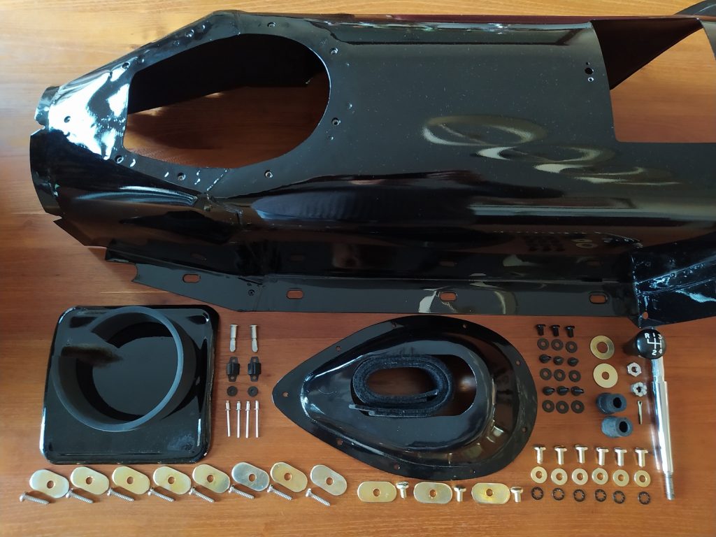
Parts needed to rebuild and mount the gearbox cover
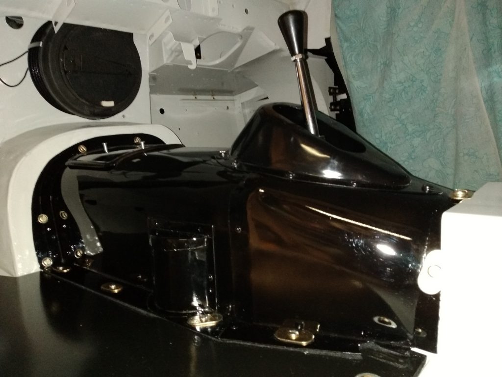
Gearbox cover mounted on the left and right floor boards

 Posted by at 16:21
jun 152016
 

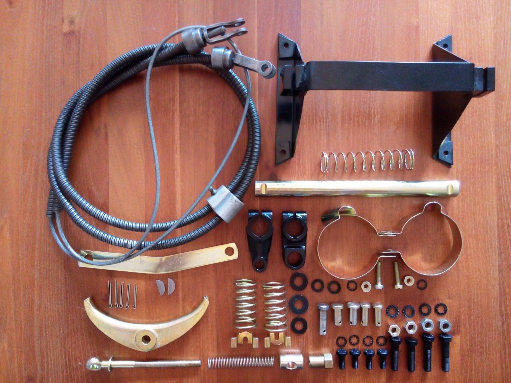
The last part which should be mounted, before the body can be placed back onto the chassis, is the hand brake cable mechanism. The parts inside the rear brake drums are already mounted (see Rear Brakes / Wheels) but the connection between the rear drums and hand brake lever not yet.

HandBrakeParts

Parts needed to rebuild the handbrake cable mechanism

The cable itself was still in very good condition. After it was thoroughly cleaned it’s ready for a next round.

HandbrakeFinished

Handbrake mechanism mounted onto the chassis 

 Posted by at 16:11
aug 292017
 

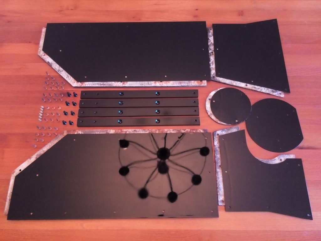
To prevent that the heat from the outlet will heat up the floor, heat shields are provided on the underside. The heat shields are made from asbestos and are covered by a thin layer of aluminium to prevent the asbestos from crumbling. These aluminium asbestos protection plates where corroded and need to be replaced by new ones. The asbestos shields are still in good usable condition and will be reused.


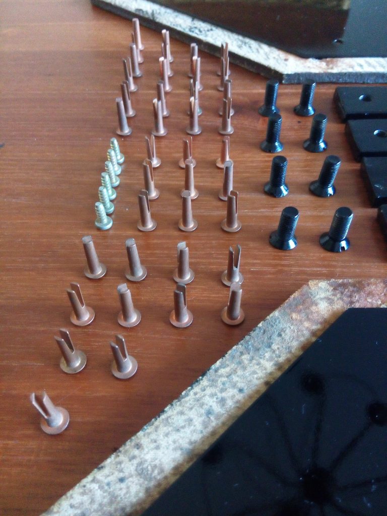
Because the rivets, used to mount the asbestos and aluminium sheets to the steel floor, can only be used one-time I started to search for them on the internet. After some time I discovered a bunch of brand new, by Jaguar so called, “Bifurcated Rivets”

 Posted by at 14:27
mei 202018
 

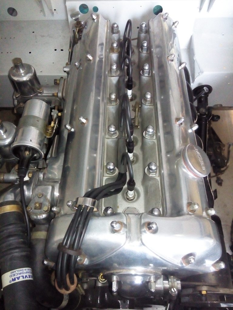
One of the last parts needed to start the engine is the distribution and ignition. The last parts will be the fuel pump and some small missing parts around the timing and choke functionality.

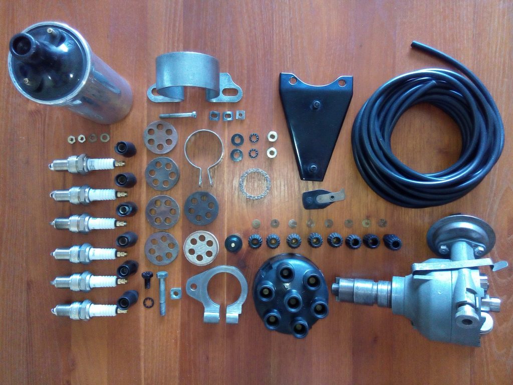
Parts needed to rebuild the distribution and ignition

During installation of the ignition coil bracket I found out that the right upper corner should have a chamfered edge. This part has been bought new because the original one was missing. With the current shape the throttle axis hits the bracket at the location mentioned before.

The clamp used to fix the distributor on the engine block was also missing. After several attempts, to buy an used or new one failed, I decided to make one myself. The nut and bolt, shown on the left side of the clamp, are reused from a different wrong model clamp.

Distribution parts mounted

Ignition parts mounted


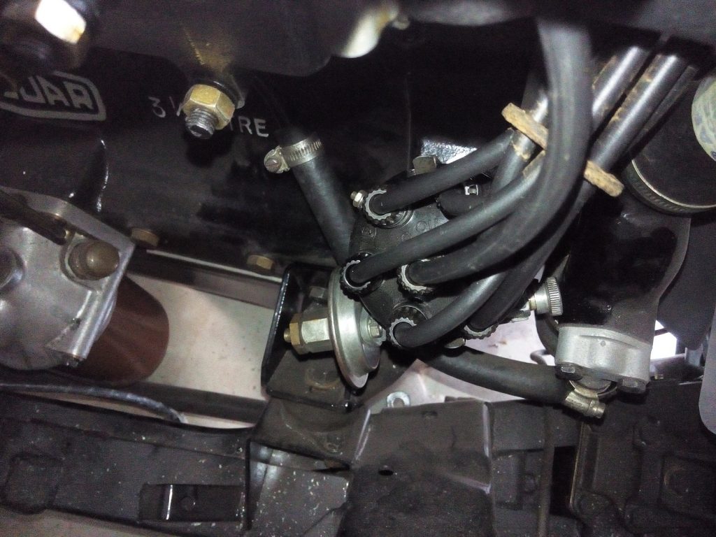
The ignition sequence is 1, 5, 3, 6, 2, 4. Plug number one is at the rear of the engine, number 6 at the front.
Cylinder 1 and 6, 2 and 5, 3 and 4 are moving synchronous. They also switch between the front three cylinders and rear three cylinders between each ignition. (Most probably to get a good distribution of the forces on the crankshaft) So this is the reason the ignition sequence is a bit strange.

 Posted by at 14:37
okt 022012
 

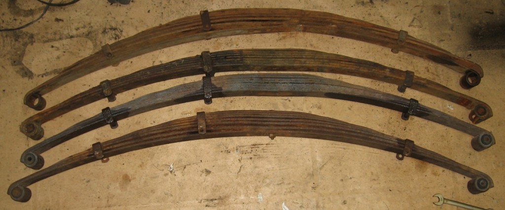
The previous owner was not able to remove some bolts and decided to cut the springs. This operation was not very successfull because at the end it was still mounted to the car. After cutting the problem bolt in three parts it was very easy to remove the leaf springs.

The original spring where badly damaged, so I had to find a spare set of original leaf springs. My neighbor, who worked that time in England, was so kind to arrange the transport back to the Netherlands.

LeafSpringOld

Two complete leaf spring sets

After bead blasting and several layers of paint they look great again. Off course all new bushing are used before mounting them back onto the chassis.
LeafSpringsNew

All separate parts used to rebuild the rear leaf springs

 Posted by at 20:43